+50, -70, -50, -1.5
Took some time in an effort to address some of the issues identified after Nationals last year. Despite the awful front suspension, my biggest problems centered around the rear of the car. The back end was skittish, never planted, and despite the stiff springs, axle wind-up was still a problem. In reviewing lots of video, the car basically never pushed, and there were frequent mid-corner corrections anytime there was a bump.
I sought to lower the car, make the rear more compliant, shift balance towards understeer, and improve axle wind-up if possible.
Review from before a set of Global West’s most race-oriented leafs, alongside some composites I’d had made.
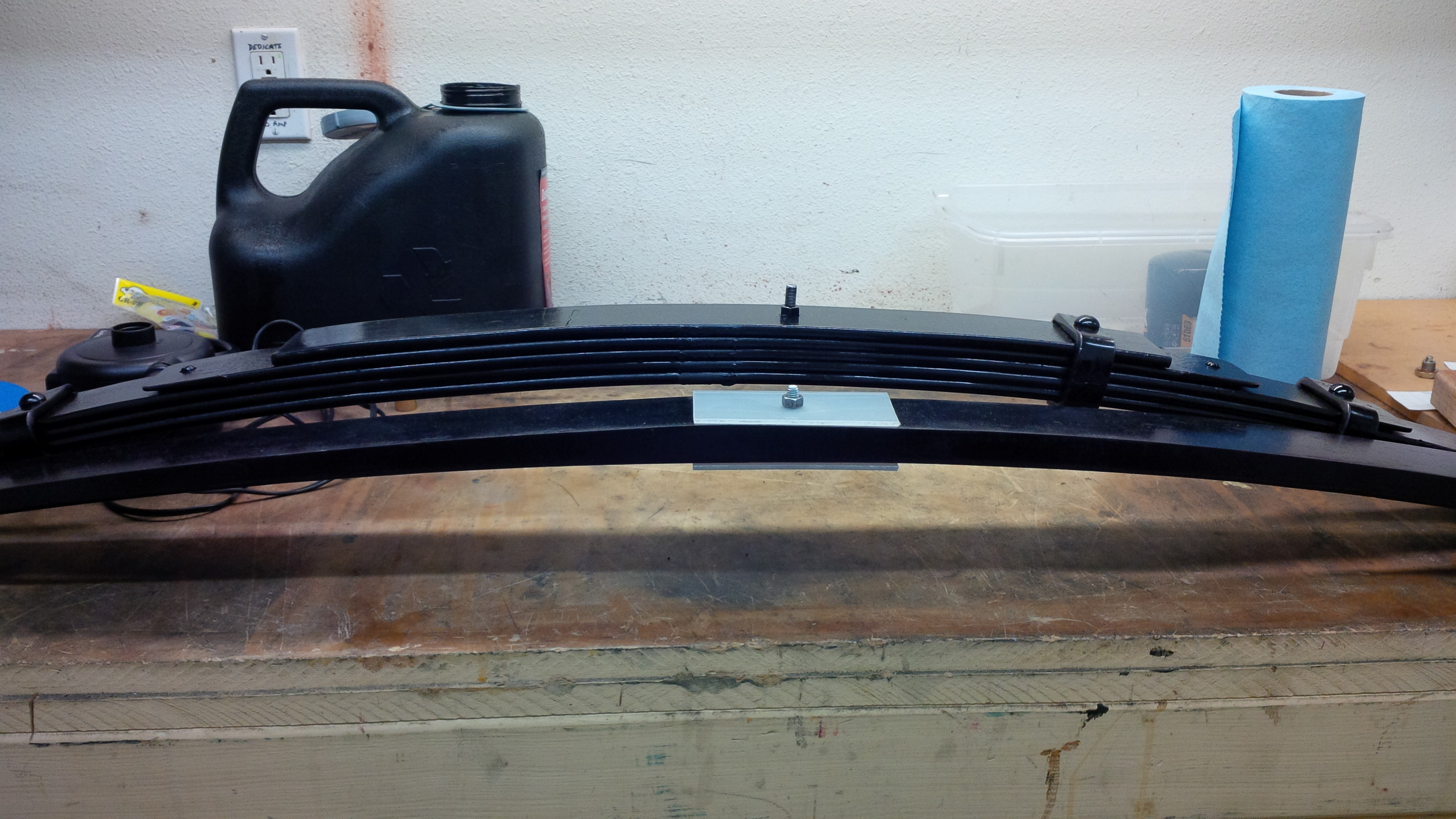
The G-W springs were a classic 5 steel leaf pack – the pair is at least 50 pounds heavier (+50) than the composites…probably more like 60-70 pounds. They were also way too high – even with spacer block, the composites were too high. The composite maker couldn’t make them any lower. The problem is, I needed a leaf spring that was about flat at ride height – but the materials used in the lay-up of the composite leaf springs expect to always be in either tension or compression, and as the spring passes flat, things go the “other way”, which would damage the spring.
An advantage of the heavy steel leafs is they can have their shape changed – so that’s what I did. Found a place in town that dealt exclusively in leaf springs (thank goodness for the Camaro, trucks still use them!) and had the leaf packs de-arched by 2″. For starters with this pack I also took the smallest two leafs out, which should reduce the rate somewhat – I estimate these are about 180lb/in., where the composites were more like 250 (-70).
You’d think changing these would be easy – four bolts in front, four bolts in the middle, two in the back, and they’re all pretty accessible. But of course it wasn’t, took many evenings of thrashing and effort to get it put together right.
While I was at it, also took the opportunity to measure rear shock gas pressure, hadn’t done that yet. Found this handy gauge to help- http://www.rjracecars.com/Shock-Pressure-Gauge-214308-Prodview.html
Shock gas pressure has a number of effects on the shock’s behavior. It can act mildly like a spring, and can impact the damping forces. In further looking to “stick” the back end of the car, I reduced gas pressure from 150 (where it was) to 100 (-50).
End result looks pretty good though, rear ride height has been reduced by an inch and a half (-1.5).

Lowering the rear also lowers rear roll center, to about where other live-axle experts say it should be.
So, to sum up the changes:
- Softer rear spring rate, ~30%
- Lower rear ride height, ~1.5″
- Reduced rear gas pressure, 33%
- Lower rear roll center, ~1.5″
Plus it looks better now!

Turning over some new leafs
Most people think of a leaf spring suspension as a drawback, and in many ways it is, but I also find it one of the more interesting challenges in developing the car.
Unlike a traditional coil sping – which is only responsible for holding up the car – leaf springs are multitaskers, as they control axle location and wind-up, in addition to holding up the car.
The original composite leaf springs for the Camaro had it way too high – might be ok for a stock-height car, at a much-heavier-than-stock rear weight (which my car is not) – so, about 3″ too high, even with a 1″ spacer block.
The next set, what’s on the car now, was better – the lowest ride height Camaro design Flex-a-Form makes. They require only about a 1.5″ spring spacer to get the height correct.
Unfortunately while spacer blocks are an easy way to get ride height where you want it, the more you use, the more they detract from the leaf spring’s ability to control the axle. I already saw in San Diego (and at El Toro for the 1 run where the car was launched with full power) that these leaf springs could not adequately control the axle as installed.
One solution is to install a torque arm system. These are big beefy (Steelitis anyone?) members that rigidly connect to the axle housing, and run forward, up to a crossmember by the transmission, which manage axle wind-up under acceleration and braking. Big, heavy, and difficult to implement legally under ST allowances – things to be avoided if possible.
So instead of a torque arm, trying instead to manage the situation better, with a new set of leaf springs. There’s a couple aspects of spring design that can help.
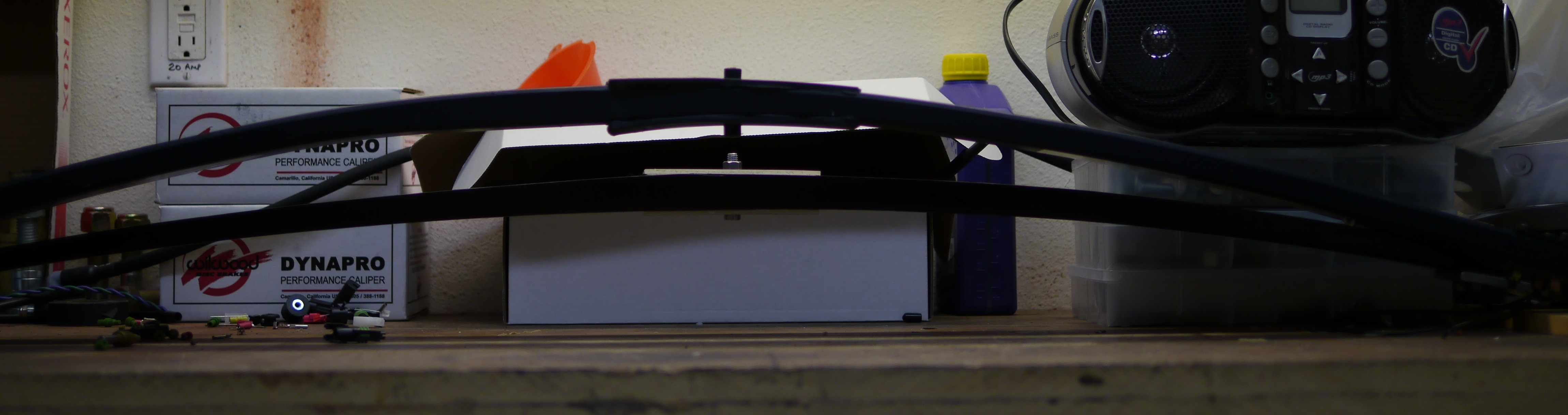
One is to make them flatter, to enable the use of less spacer block. Since Flex-a-Form had already made their lowest possible ones on their regular Camaro die, they had to try something else, which was the use of a different die, used for transverse Corvette springs. This produced a flatter spring, though in looking at it next to one of the original Hypercoils, am not sure it is flat enough. Will have to get these on the car, to see how much spacer block is needed – hopefully little to none.
The other thing, was I had them make the forward section of the leaf up through the spring mount area, extra thick, while thinning it out in the rear section. The middle and forward section of the spring are the portions most responsible for longitudinal location and managing axle wind-up, so some extra beefiness there should bolster those strengths, while the thinner rear section keeps the overall spring rate in the right range (approx. 250lbs/in. for now).
How proportioning valves work in Street Touring
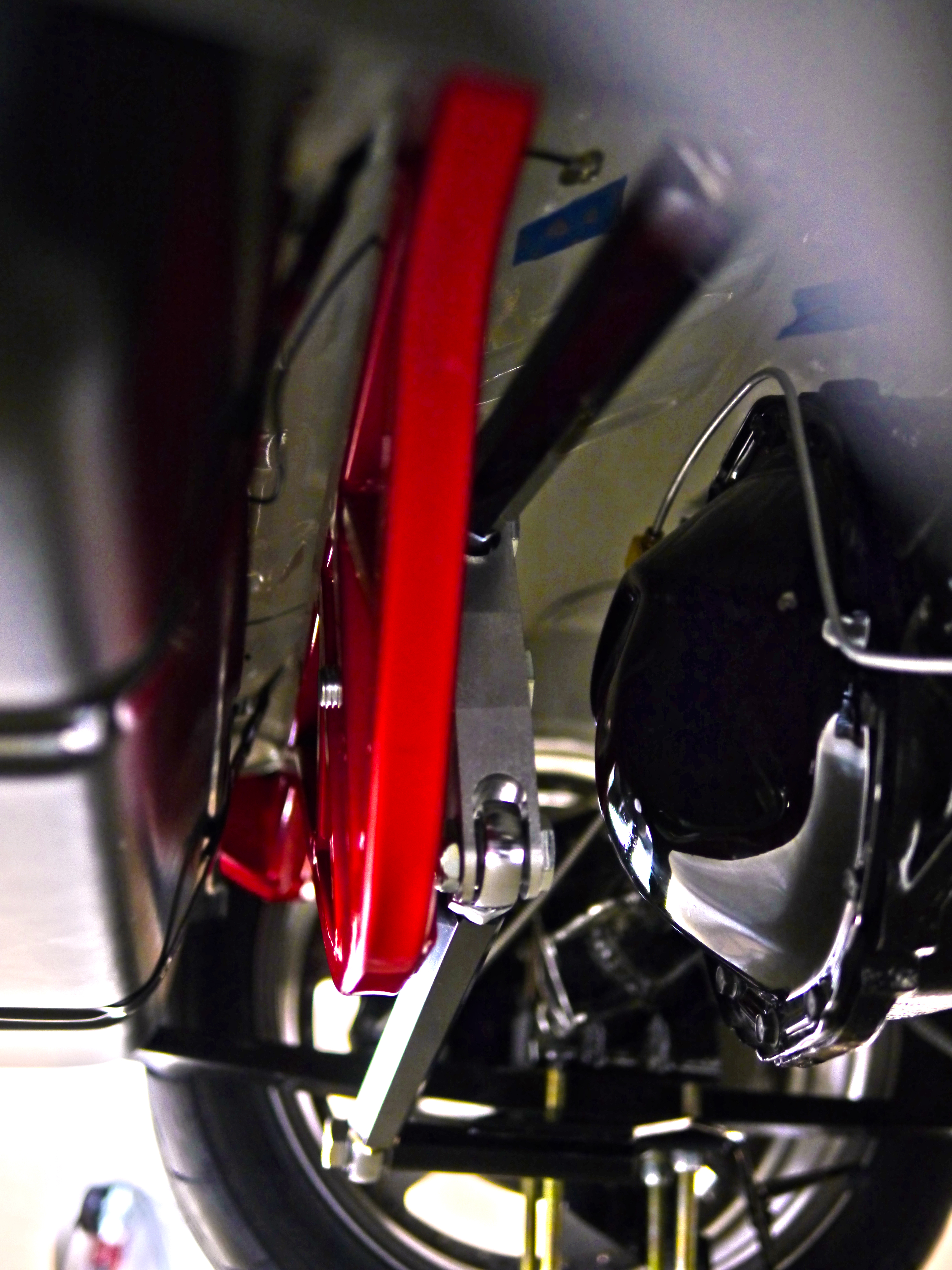
Actually the Camaro’s brake bias was probably too far off to be fixable with a brake bias adjuster, so it’s getting a more powerful prescription:
reduced rear brake piston area.
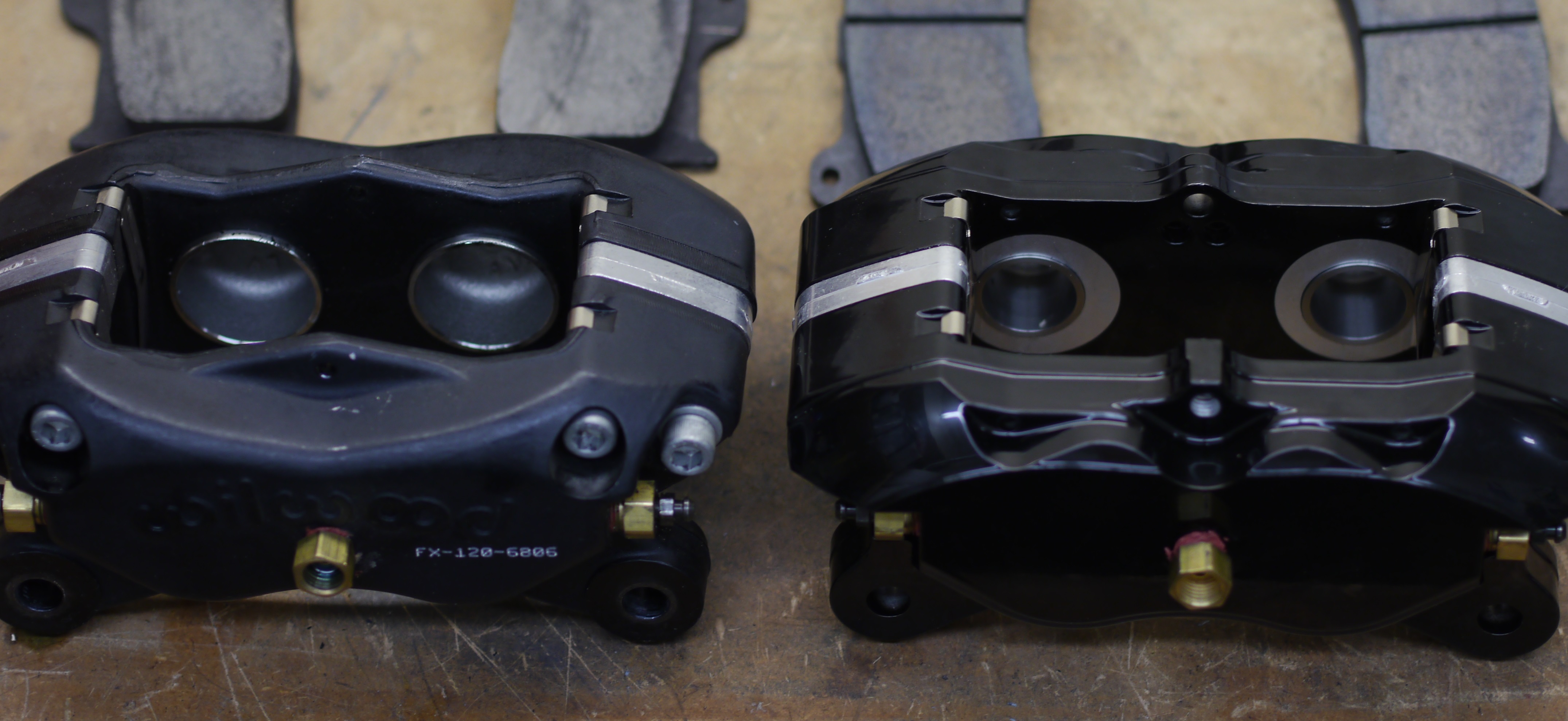
As you can see, the caliper on the right has a lot smaller pistons. Both have 4 pistons and the same pad area, with the same pad compound (same pad compound used in front).
Going to a smaller piston area may seem counterintuitive if you wanted to reduce force – won’t a smaller piston “move further” than the bigger, thus exerting more force?
In actuality, the pads don’t have far to go, and once they’ve hit the rotors, braking force has to do with the pressure exerted. The principles of hydraulic systems dictate the pressure be equal everywhere, and force can be figured as pressure applied over an area – thus, the smaller the area, the less pressure applied to the brake pad.
Hopefully that equates to less death-rotation under braking 🙂
Like the look and finish of these better anyway, they match the 6-piston fronts.
Why people use steering lock limiters
http://www.pictage.com/client/eventPhotos.do?event=1416471&category=5&page=7&oldView=pdp&pageSize=1
In it, the car is at heavy left steering lock.
In putting around before that event, I’d found with the camber, caster, and wheel spacer dimensions, I could get just less than 1.5 turns of the steering wheel, before stuff would start rubbing in the fenderwells.
I’d even noted where the rubbing was happening (wheels on the forward portion of the upper control arms) and filed the area down a little bit, figuring that’d be the worst it would get.
But then the almost-spin happened. Caught me by surprise – as, well, just about everything with the car still does. The Yokohamas don’t seem to make any sound when they are locked up, and on the San Diego surface, they didn’t seem to really make any visible smoke either.
In the save I forgot about the self-imposed steering limit of just over one turn (which I remembered in my spin the following weekend at El Toro) and turned the wheel as far as I could to the left.
Saved the spin but the results of having done so on the right front upper control arm are here:
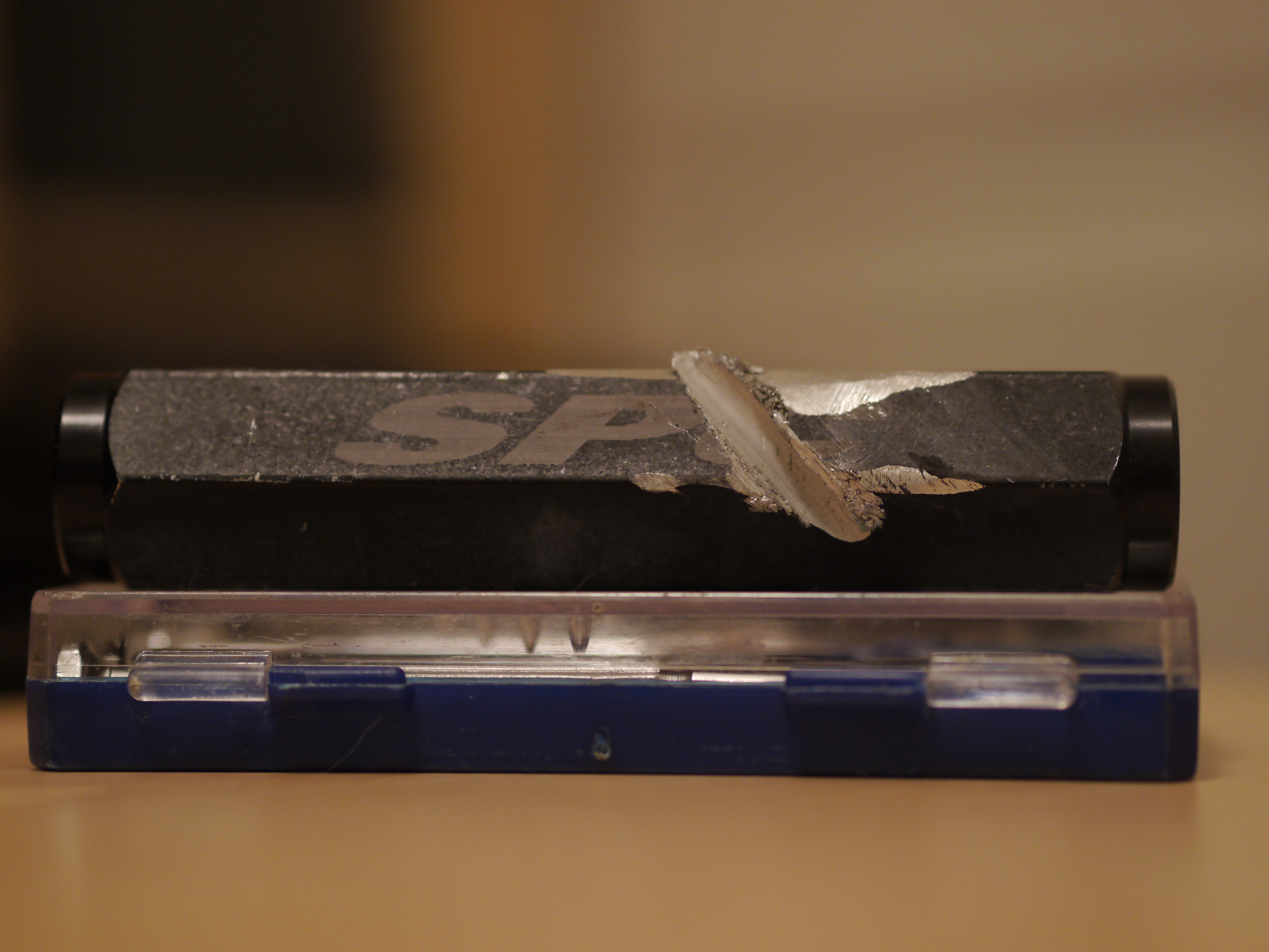
Owie!
The inner lip of the wheel rubbed right through the aluminum in the arm, almost into the threaded section. If you get the high-res pic where it just about goes through in the low points of the inner threaded barrel.
Have a new piece in there now, and the other side is ok, will have to be more careful in the future. This does highlight a nice aspect of modular arms, and of modular parts in general – instead of having to replace the whole arm, only had to replace a $19 piece, which only took a few minutes.
Jump in Bump
Got a fresh shock dyno today, this is about the most bump Penske could get with its existing internals without risking shock cavitation, even with gas pressure pushed to the limit.
Apparently they have a lot of experience with very-high-rebound setups, as it’s what all the Nascar guys use to control their chassis that run around on bump stops most of the time. But nobody seems to be going after those crazy low-speed bump forces.
(orange is baselie valving, red is new at full stiff, purple at 3 clicks off full, as far as can go without cavitating)
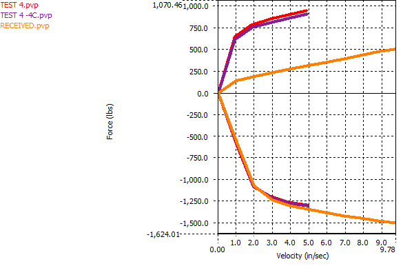
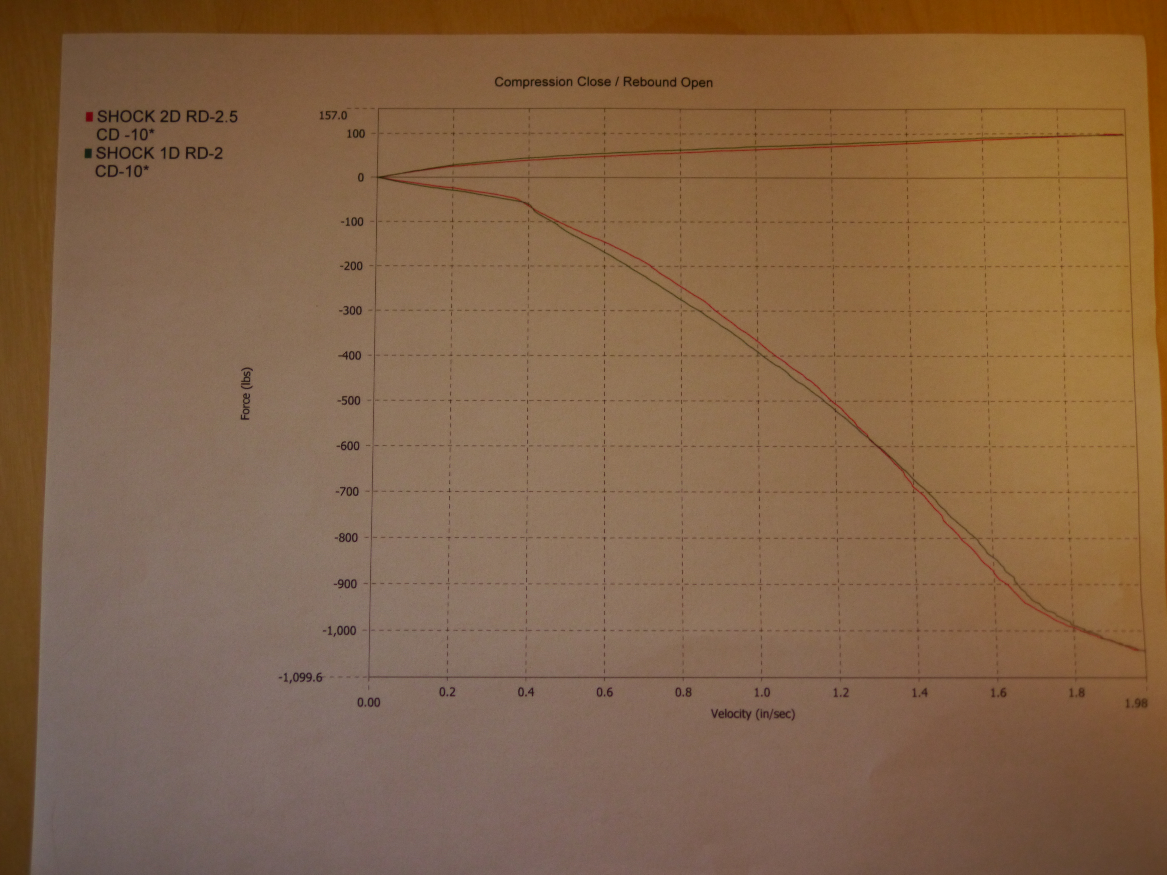
One must remember the Camaro shock is mounted about 9″ out on the 16″ long arm. You have to multiply x .316, and be looking at 2in/sec here, and compare that to the raw values at 3in/sec, you’d see on a strut car like a BMW. 240lbs. @3in/sec is maybe a bit high, but not out of bounds. Ditto 350lbs @3in/sec for rebound. But that is the horribleness of the Camaro suspension – it takes high-end modern shocks pushed to their limits, to achieve damping effectiveness on par with “normal” performance dampers on a better-suspended car. I can go a bit further with both bump and rebound with these shocks, but doing so would require changing out a lot of their guts, and I wanted to be sure to get them back and installed in advance of my next event May 19.
It’s possible this will be “too much”, and the car will want to push. I am ok with push in transitions (prefer it really), but if the car bulldozes in steady-state, I can reverse some of the other changes made (by softening the front swaybar and raising the rear roll center) to correct things in the other direction.
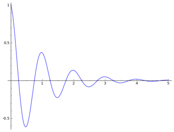
The subject of dampers has some parallels to my overall theory of car tuning. I think of tuning like a decaying, or damped, sine wave. In it, you start off at an amplitude or Y value very far from zero, which itself represents perfection. Over time, you make changes that you hope get you closer, knowing you’ll never land exactly on it – there are too many variables. But you keep making changes, and with experience and knowledge gained, begin to make smaller and smaller adjustments as you hone in on “perfection”, which is never actually achievable.
Tricky things come along like a new tire to test, or new preparation allowances, even a new surface, that move the perfection line around, and perhaps necessitate some big changes to get back to within the same distance of perfect.
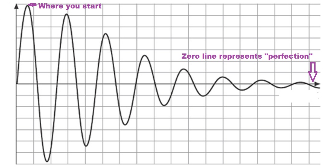
It illustrates a little bit, how you have to know what changes and adjustments to make, and be able to evaluate whether you are getting closer to, or farther from, perfection. You also need to know if the change was too big and you overshot things, or if it wasn’t enough, and there is still more to do.
Really good tuners of cars can get closer to perfection more quickly – just like firm dampers don’t let your springs oscillate too much…
I certainly don’t think I’ll be anywhere close after only 4-5 tuning iterations or cycles given how radically far off the car was to start with, but it should continue to get better and better. The difficulty in wrangling this beast both from the tuning and driving angles, is part of what makes it so engaging.
Rear brakes were definitely locking up
Found some new photos from the SD Tour, and this one:
http://www.pictage.com/client/eventPhotos.do?event=1416471&category=5&photo=2408
is especially illustrative. Note how the inside front is still blurry with rotational motion, but the inside rear is nice and sharp…
Looks pretty sharp in the next couple as well, as the car begins to pirouette. Barely caught it.
Looking forward to the lower-piston-area rear calipers. Feels good to have an in-car impression validated with external data.
p.s. I would have bought the digital copy and posted it here – but the photographer wants $40 per digital image? The nice image I used from Late Apex Photo in the last post was a reasonable-for-a-great-photo $7.50…
Shock installation
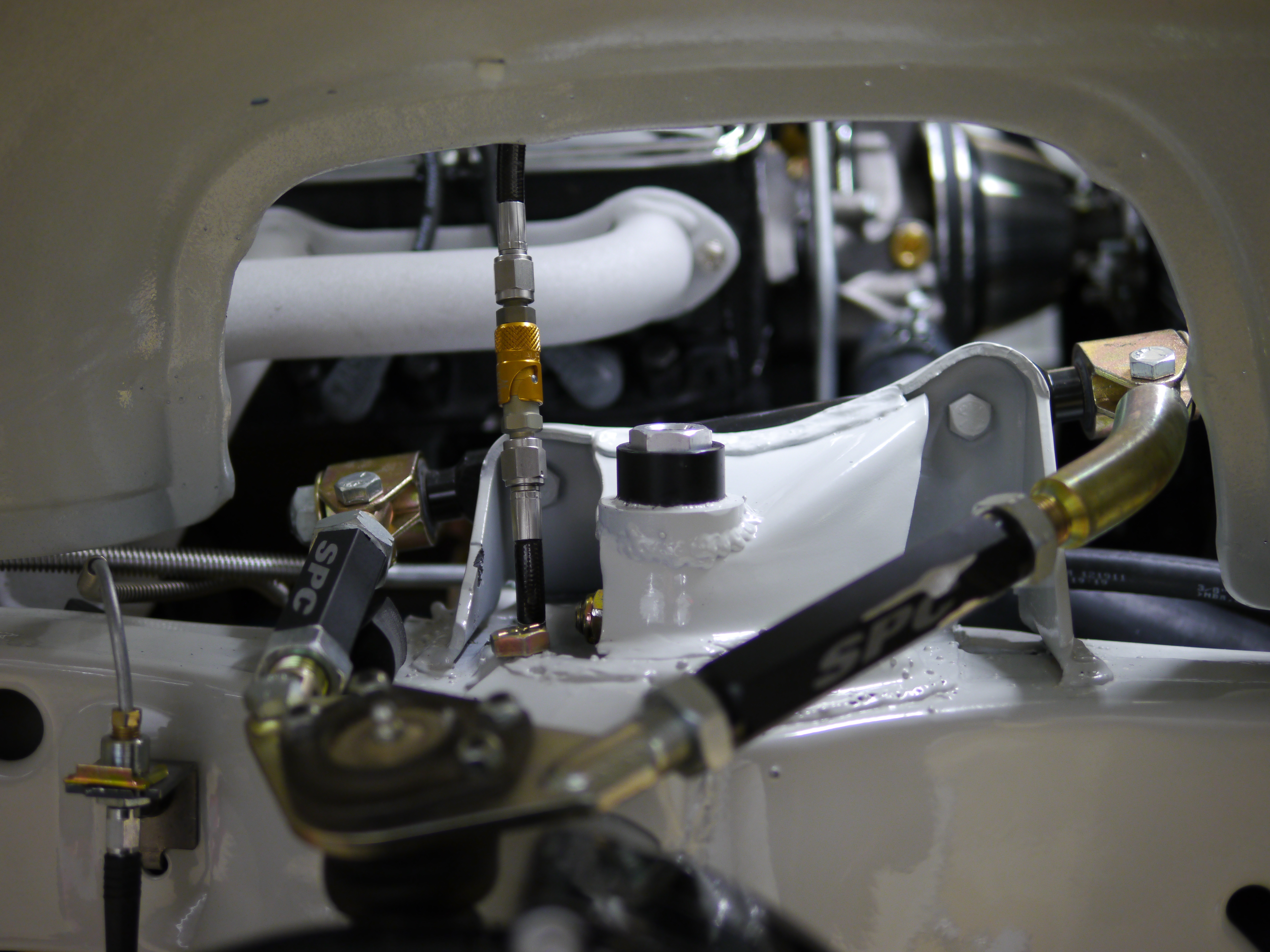
Finally got the rear shocks all buttoned up-
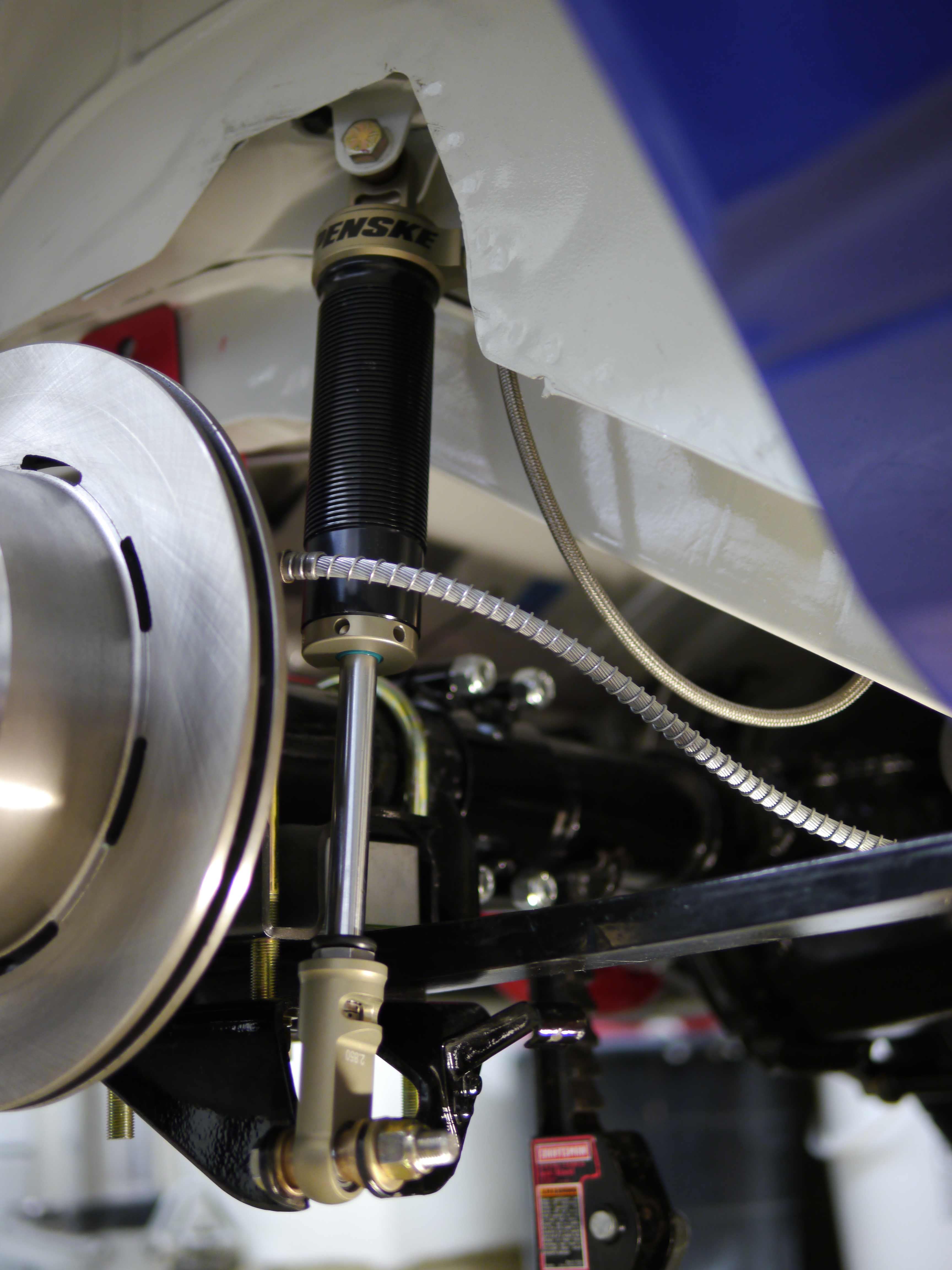
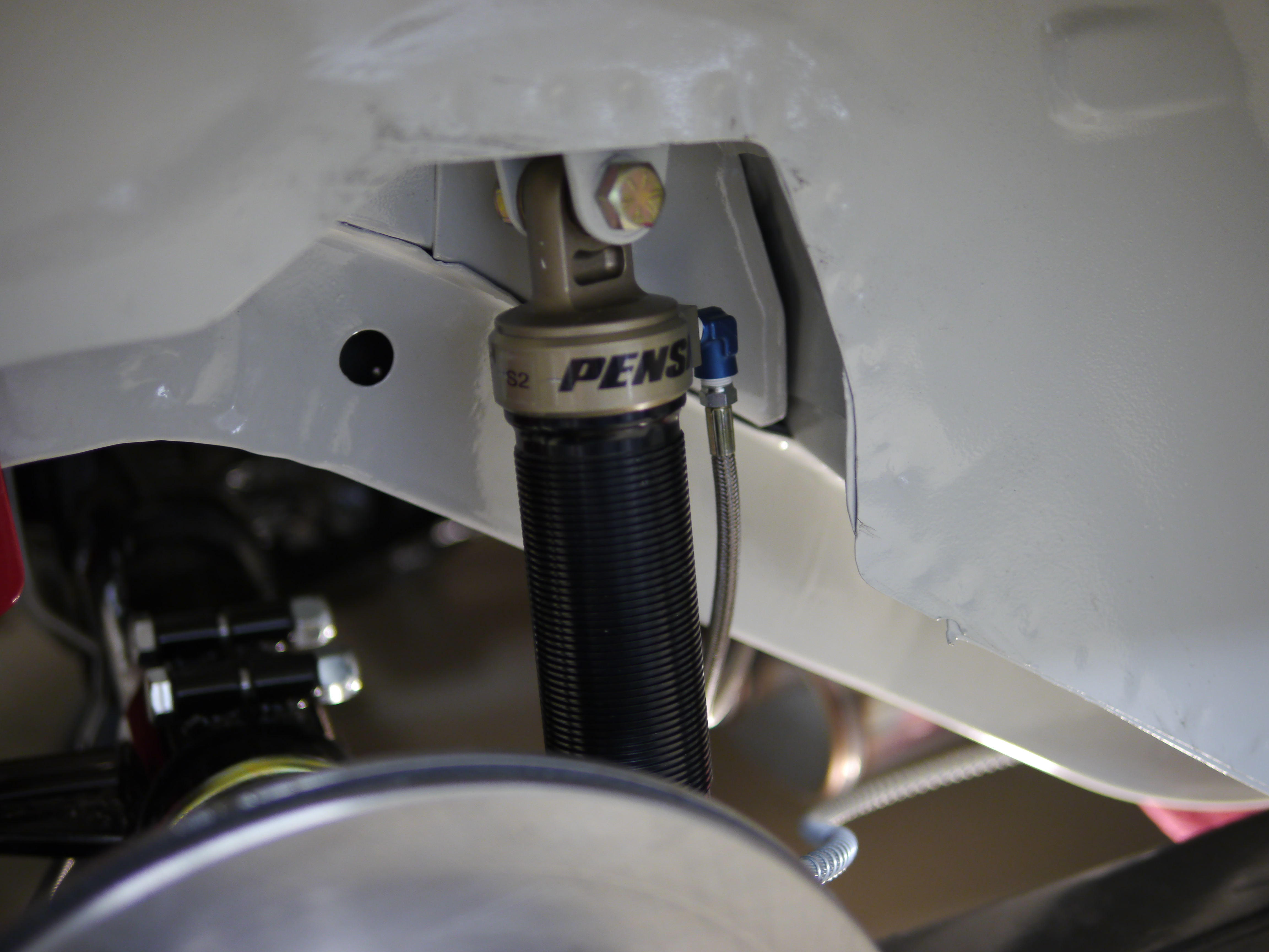
Not a ton to mention that isn’t obvious from the pictures. Shocks are mounted inverted, which helps reduce unsprung weight a tiny bit. In this case it also means the remote reservoir hose doesn’t move as the suspension moves through its travel, which should be a good thing for the life of those components.
Since the rear swaybar is a no-go at this ride height, was able to re-use the swaybar mount holes for little canister mount brackets. Really happy the length of hose to the remote cansiters, and the way it bends around the frame rails without touching anything – worked out perfectly.
The rear shocks have four adjustments, in two locations. Rebound and “shaft” (better come up with a better name for that, too likely to be the target of jokes) adjustments are in the window where the lower shock eyelet mounts to the leaf spring plate (as an aside – note this shock mount plate puts the shock in double-shear – most run the crummy single-shear plates) and adjustments for low and high speed compression are those two knobs at the top of the canister – not the easiest to get to but reachable if you lie beside the car.
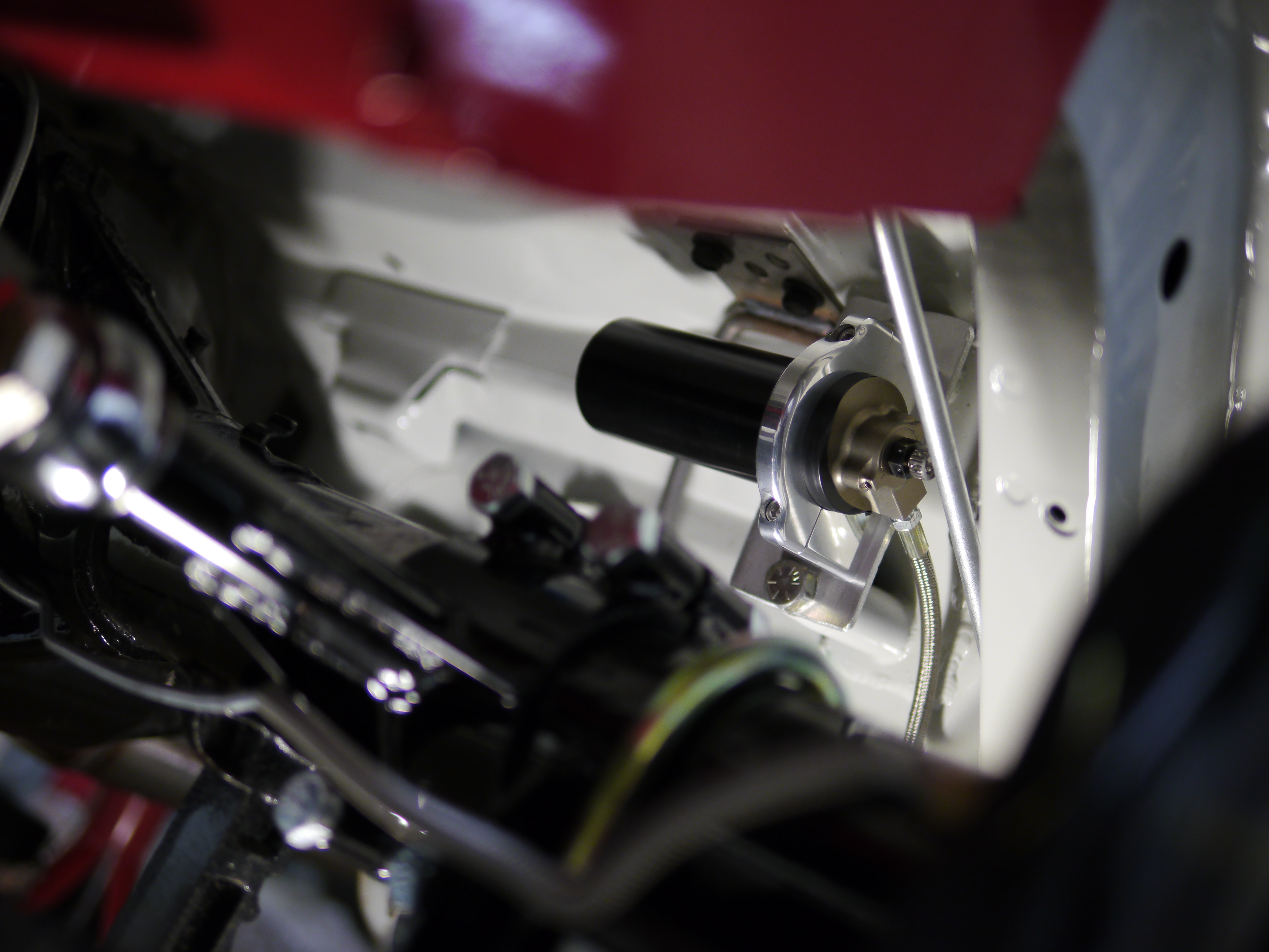
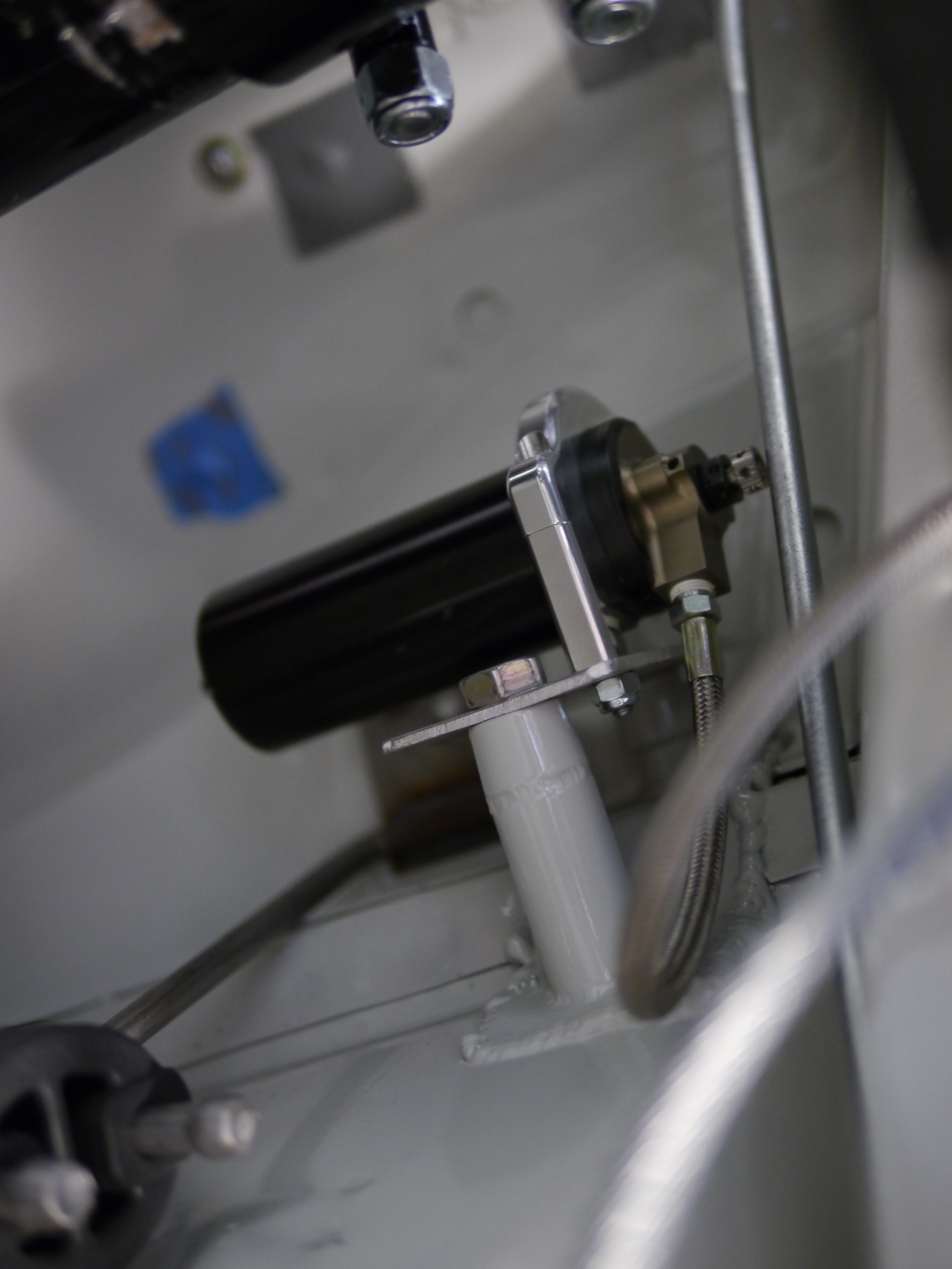
Up front, the shocks are so buried, there isn’t much to see. These things were a packaging nightmare!
Here too they are inverted, which provides the same benefits as the rear. Though in this case it’s more a matter of packaging necessity, than preference.
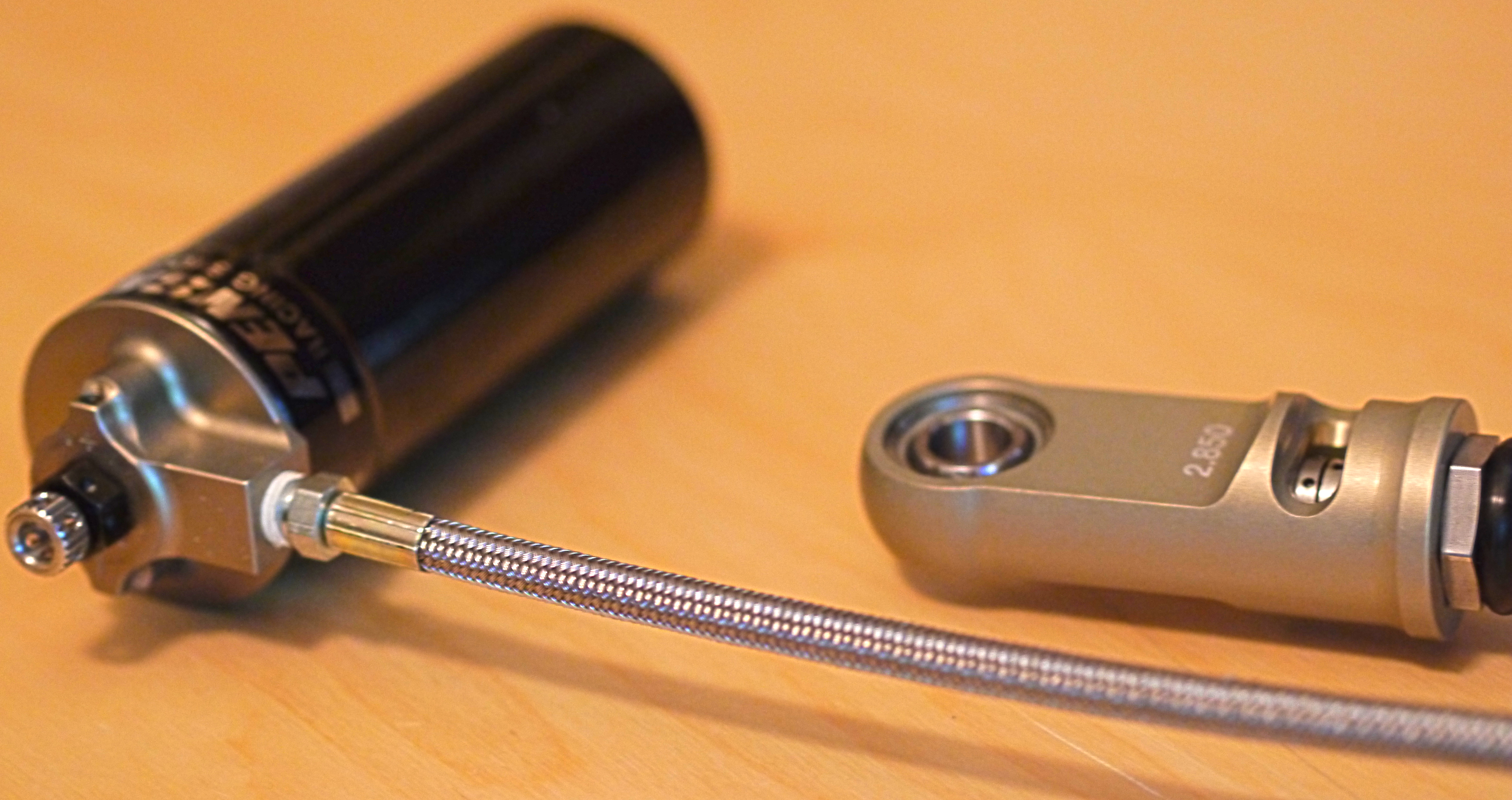
Since one of the advantages of these sorts of shocks is the bling factor, and the fronts are basically totally hidden, here’s a couple pics before they went on the car:
Complete shock – 8760 body with 8300 canister
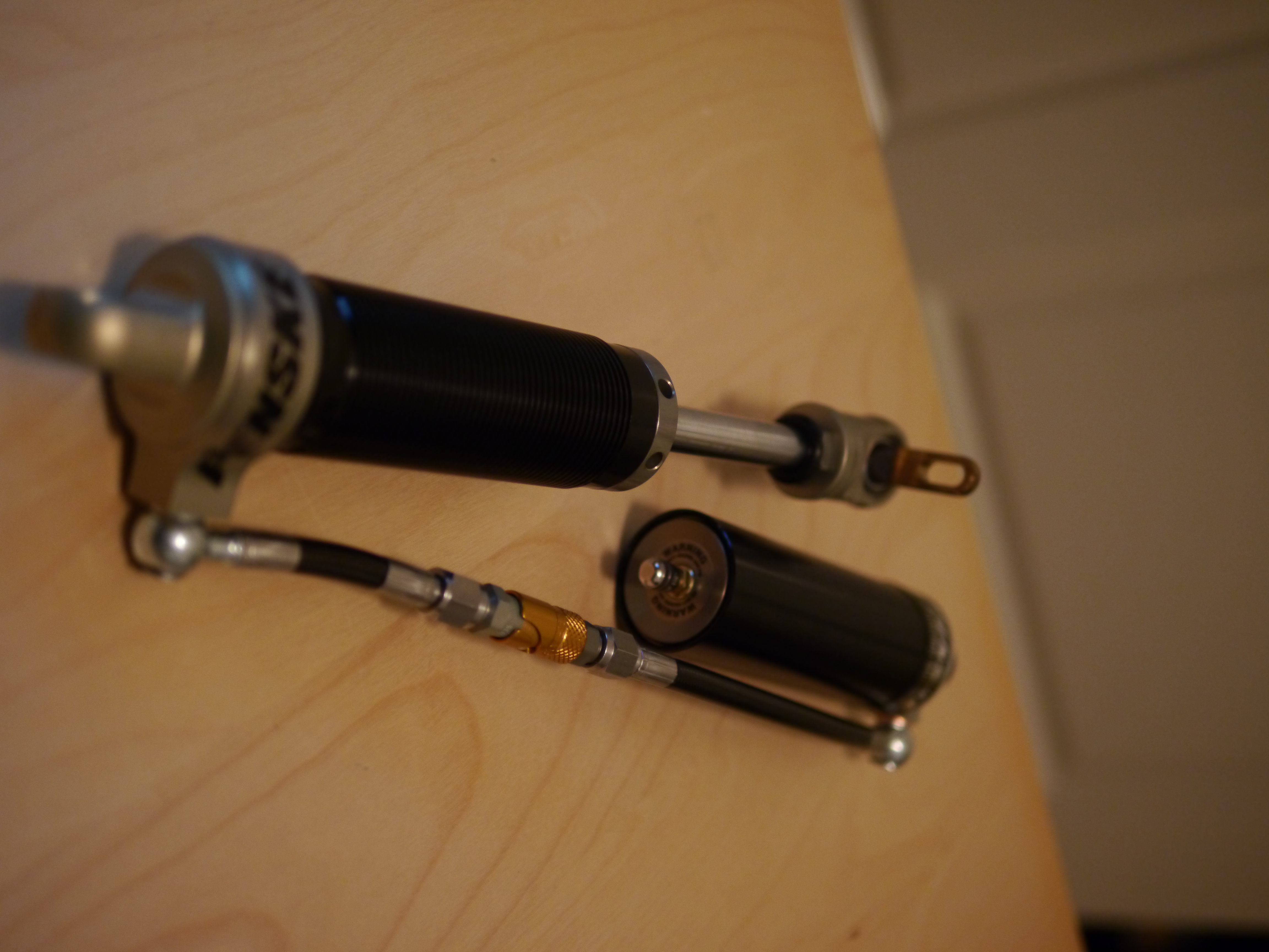
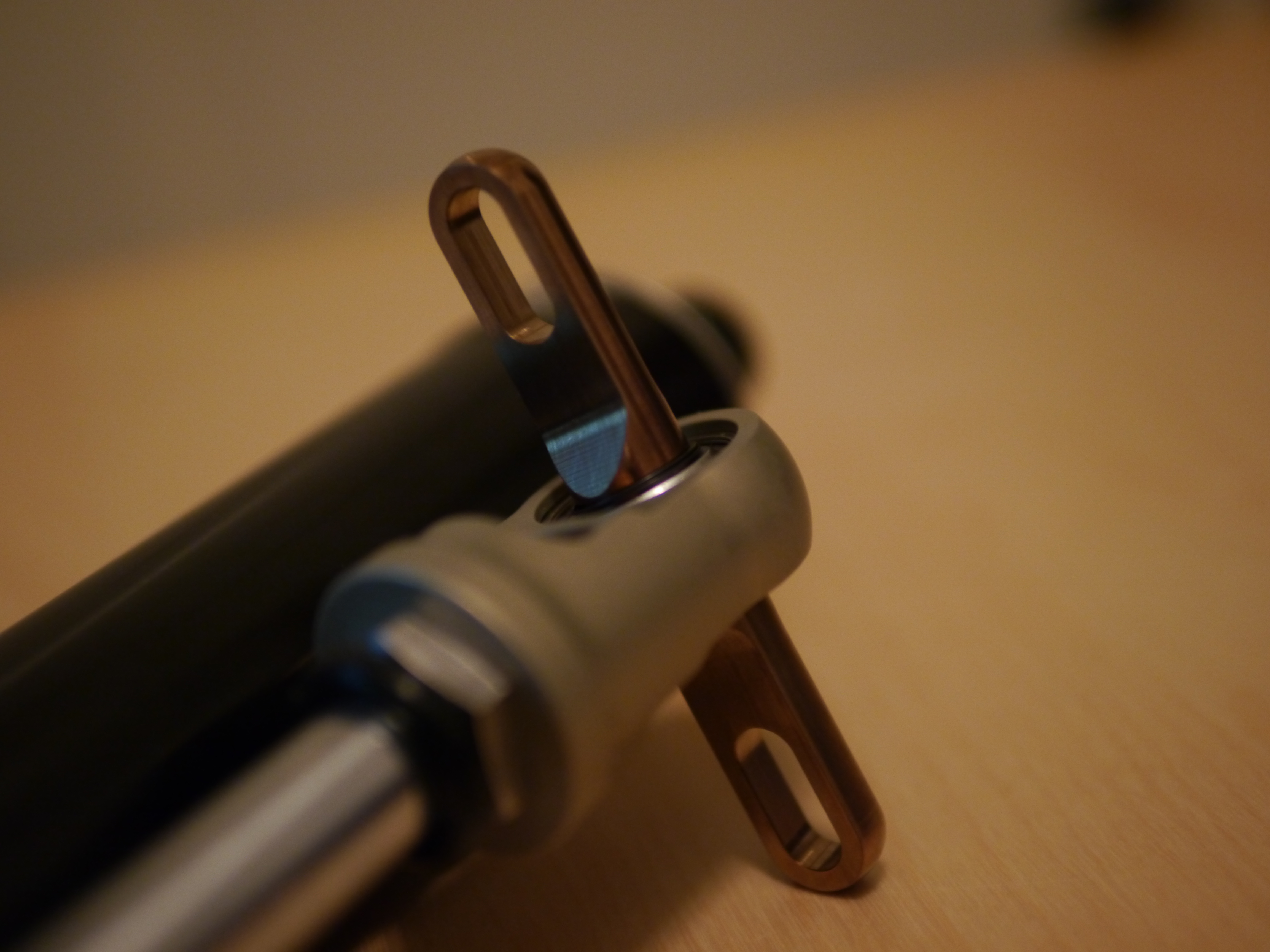
T-bar
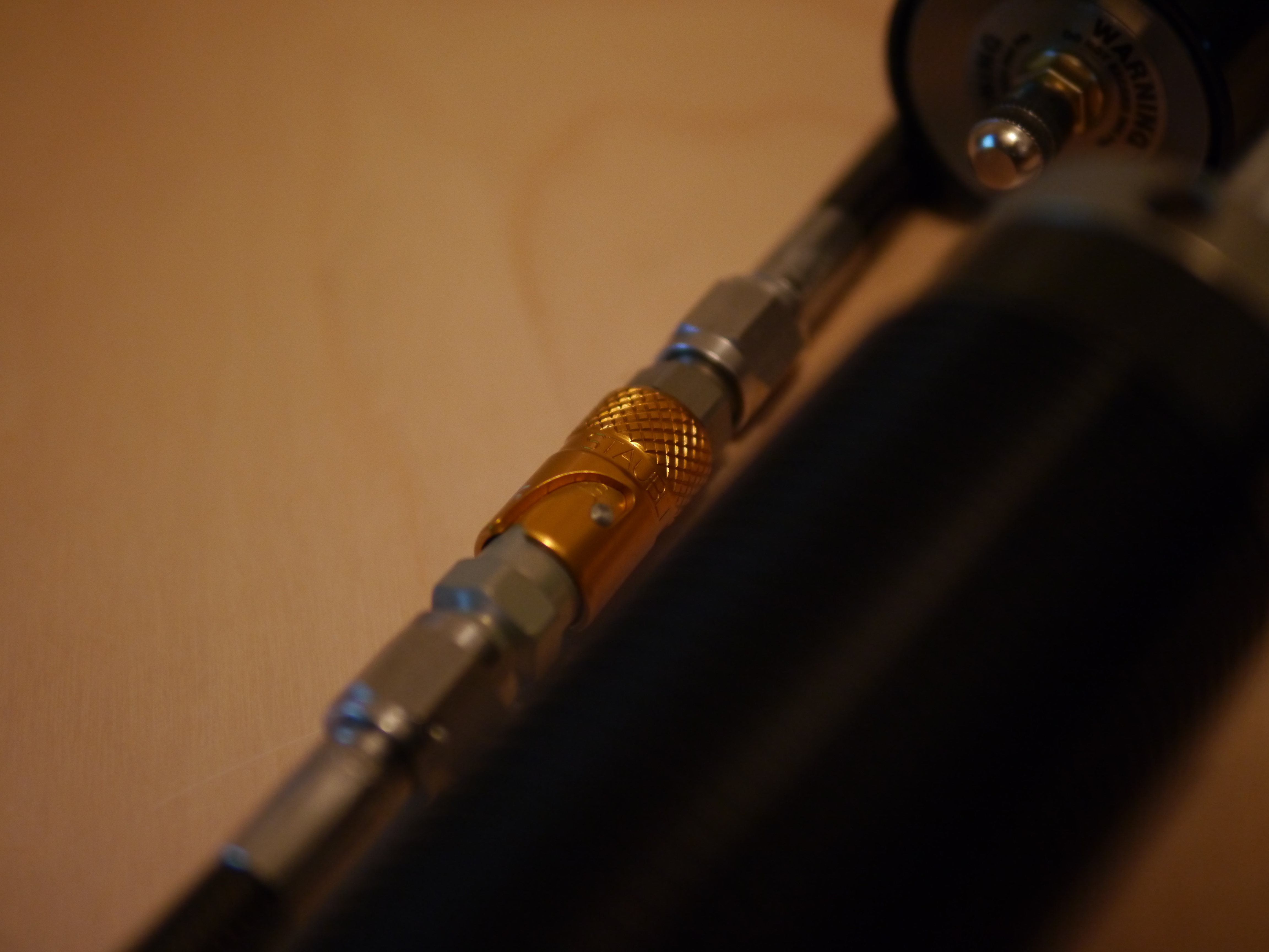
Staubli quick disconnect
And on the car, buried as can be-
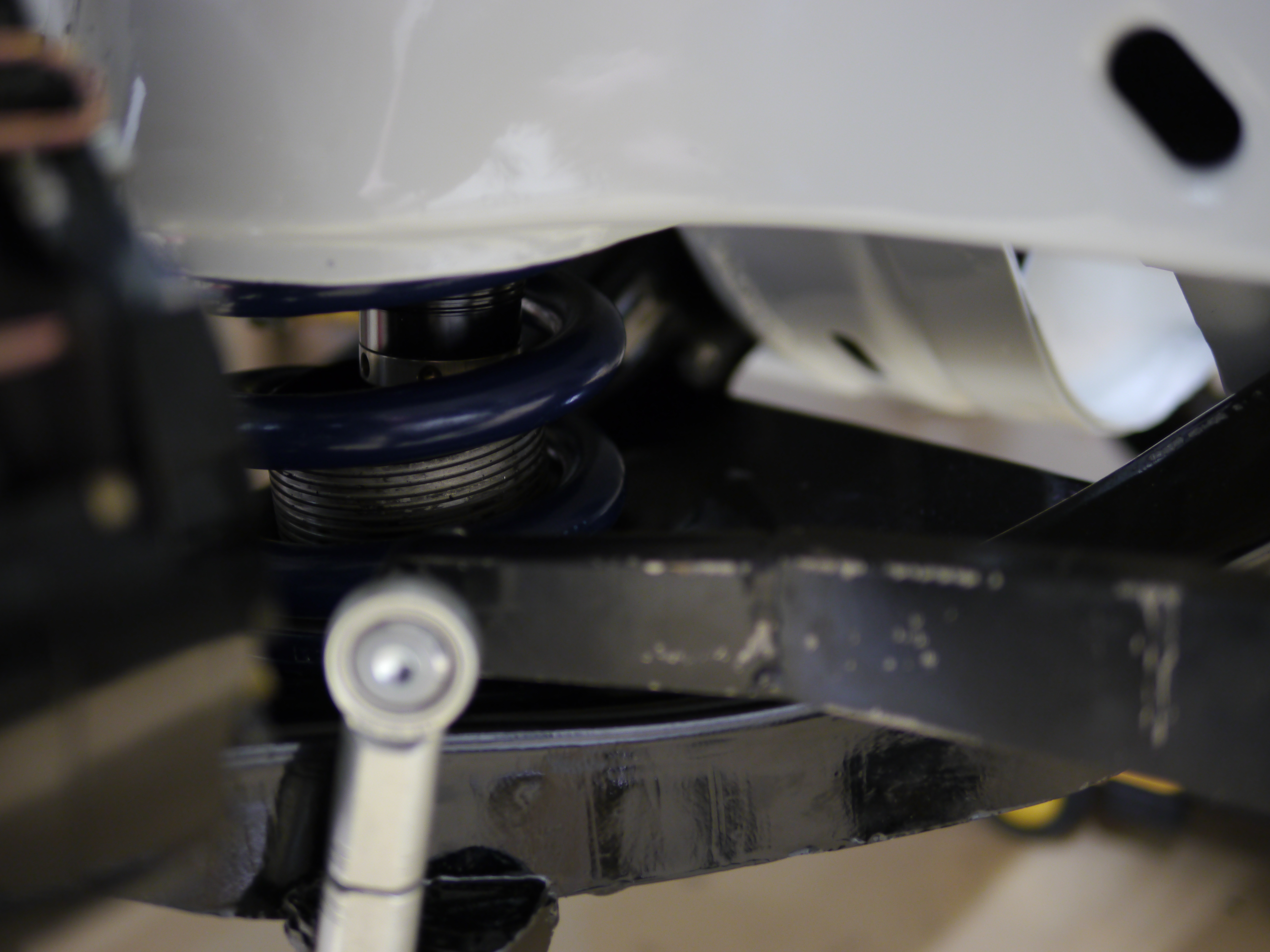
Thank goodness I chose the smaller 45mm bodied 8760s – they just barely clear the rear spring adjustment cup at full droop. To provide room for the remote reservoir nonsense, had to run a 1″ horseshoe-shaped spring spacer up top, which for now meant completely removing the ride height adjuster at bottom. To regain that ability, will need to get shorter springs, or cut these ones down a little.
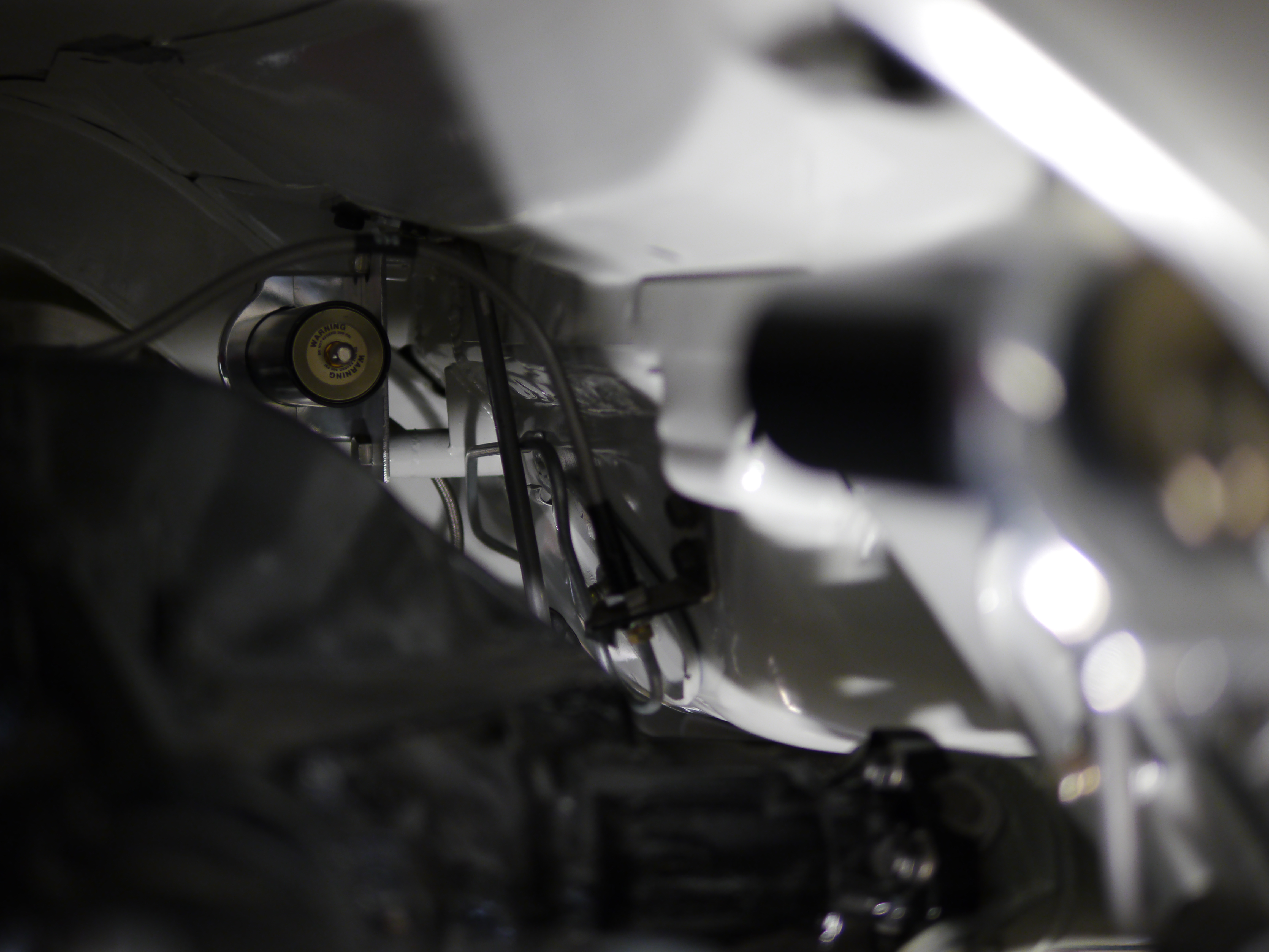
The canister is in a super-temporary spot until I figure out how to mount it in the engine compartment.
Front adjustment of compression will require opening the hood to turn the knob on the canister. Rebound will require tools, as the “window” with the knob inside is buried in the lower control arm. I’m going to change the way it attaches from this draft (which is approximately version 4.7) to allow the adjustment to be made with only one tool, and not require raising the car or any other disassembly. I probably won’t change front rebound that often anyway, leaving it at max and hoping it’s enough. The front shocks are capable of really big forces, but those forces drop off very quickly as the adjuster is moved away from full.
Speaking of those forces, here is a dyno of the front shocks, or at least, a portion of what they can do – note the x axis ends at 2in/sec. 🙂
Rear Shocks
This week both front and rear shocks arrived for the Camaro.
Despite my history of nothing but satisfaction and success with the 28-series Koni shocks, for this car, I have chosen to give the Penske platform a try, for a few reasons-
- They offer some more modern valving options not available in the typical 2812Mk2 bodies I’ve run. Will explain that below.
- I do have some experience on Penske triple adjustable shocks – the Lexus IS300 owned by Jason Uyeda I drove a bit in 2005 had them, and they worked great. Also, Doug Hayashi’s Honda S2000 we ran in the 2003 Open Track Challenge had a set built and valved by Erik Messley, and that car was sweet too.
- The people I use to build my shocks, ProPartsUSA, has experience with Penske, and would be able to help me out. I wouldn’t have tried this were it not the case.
- I need *some* excuse to run some kind of Penske sticker on the car. The classic Trans-Am cars always had “Penske-Hilton Racing” or “Penske-Godsall Racing” on the front fenders – if I put “Penske Racing Shocks” in the same spot, should give it the look without being totally illegitimate. Of course advertising for people when you don’t have to (not like anybody is cutting me deals) is kinda silly IMO so who knows what will go there.
What actually got me started down this path was ProParts mentioning they had a set of very high-end 8765‘s sitting on a shelf that they’d used for a test but never on a car, that they could pass on for a very good price. Their dimensions put them in range for the rears, so they proceeded to build them.
Not having built/tuned a live axle car before, many aspects of what comprises an “ideal” rear shock valving are at this time a mystery to me. Some things are known – spring rate, ride frequency, and motion ratio – which, unlike so many aspects of this chassis, actually isn’t a problem. It is basically 1:1 in bump, and close to it in roll. I also know my own preferences – which in general, are to run the rear shocks fairly soft. Too much rear compression, and you risk “blowing the tires away” with a rapid throttle press. Too much rear rebound ups the chances of losing the rear end in a transition type maneuver.
Of course, too little, the car feels dead, and difficult to make “dance” through tight spaces, of which we have plenty in autocross. In my experience if you have a fairly well balanced RWD chassis (either naturally like a Viper or with freedom over bars and springs like an STS 240sx), softer rear shocks are something that makes a car easier to drive, helping you minimize the frequency and magnitude of mistakes, even if maybe it sacrifices ultimate potential a little.
All that said, here’s a few dynos of the rear shocks-
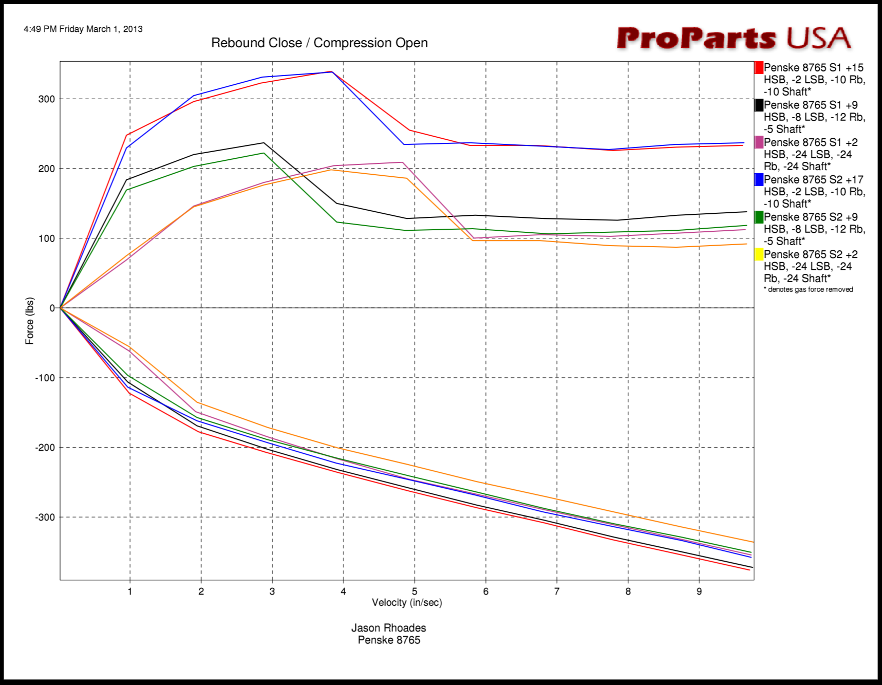
On the rebound side, we have modest forces, and a mildly regressive curve. This shock will be operating around 3in/sec for typical (non-bump) autocross maneuvers. I would have like a slightly wider range of adjustment with another 20% available both below and above this range, but all told it’s probably about where it needs to be anyway.
Things start to get really interesting on the bump side, and this is where the 8765 separates itself from the more-common 8760. Note in the legend at the upper right, there are four dimensions given for each dyno:
- HSB
- LSB
- Rb
- Shaft
Aaaack! Four adjustments?!?!?! In the picture above notice there are two wheels in the eyelet at the end of the shaft, and there are two knobs at the end of the canister. At the other end of the canister is the Schrader valve for gas pressure, which one could even consider a fifth adjustment – oiy.
For those that haven’t seen it, here is what I consider an excellent, clear and concise guide to shock tuning by Neil “Fireball” Roberts:
http://www.ozebiz.com.au/racetech/theory/shocktune1.html
There are some people who will feel that aspects of this are incorrect, but for me, it has worked, and it fits in well with what my gut/intuition tells me is happening at each tire in different phases of the corner.
Now, when Neil talks about bump and rebound, he is talking about their low-speed elements. High-speed shock tuning doesn’t usually come into play for tuning handling – it does change how the car works over bumps though.
On the compression side you can see these shocks have an unusual shape – the compression force actually drops at a certain point. This is known as “regressive” valving and was pioneered in F1, to help keep their chassis from getting upset when the cars hit curbs. This allowed them to continue to have big low-speed compression forces to manage the aerodynamics better, but then have a chassis that became super soft and compliant (relatively speaking) when presented with a big obstacle.
We don’t have curbs in autocross but our sites do occasionally have bumps, and in theory this approach should help keep that big heavy rear axle more compliant over those bumps, while still providing a good measure of traditional low-speed control.
The additional adjustment (“Shaft” on the shock dyno) interacts with the High-Speed-Bump settting, to determine at what shock velocity things “blow off” into regressive mode.
Part of what made me interested in this capability in conjunction with a live rear axle car, is the shock’s contribution to axle torque management. The car depends on its leaf springs to control axle wind-up under acceleration and braking. In ’67 the rear shocks were laid out in a “non-staggered” arrangement, with both lower mounts ahead of the rear axle. These cars were notorious for bad axle tramp, and as a partial remedy, in ’68 the shocks were “staggered”, with one lower mount of the shocks ahead of the axle, with the other behind. So, in a ’67, both rear shocks are in bump under acceleration, and rebound under braking.
When a car is accelerating, the front of the diff wants to rotate upwards, which wants to twist the springs in side view. The much-stiffer-than-stock (approx. 3x) springs I’m starting with will help this somewhat, but the big (1.5″) spacer block hurts, as do the high-grip tires and increased horsepower.
Axle tramp or hop is a violent condition when a wheel/tire begin to bounce, suddenly becoming loaded then unloaded. Not only does it kill acceleration off the starting line or out of a corner, it can also destroy the beefiest of parts. For an example of how it can look, check out the 1:13 mark of this Mustang driver being a hooligan on the streets of San Francisco – granted that was in reverse, but the principles are the same.
Axle tramp can be cured with 75lb. torque arm setups, but I’m hoping that with this range of valving characteristics, it can be sufficiently mitigated with the right shock settings. Sometimes, stiffer valving isn’t the solution.
Sorry not much picture content at this time – have the rear shocks mounted on the car, but the remote reservoir canisters are dangling loose. Darn those canisters!!!
Watt a pain in the…eye?
Well, that was an awful weekend last weekend.
Thought I’d gotten through all the really gnarly work, but prep for the Watts turned out to be one of the toughest weekends yet, for a few reasons.
One, it was unusually cold in San Diego – not that it ever gets really that cold here, but there was a frost advisory with overnight lows in the 30’s. Enough to make lying on the garage floor feel a bit like lying on a hockey rink…
Two, it was a bit challenging psychologically. With composite leaf springs in the rear, the car has to have some kind of dedicated lateral axle locating device. I set out to cut away a perfectly good one, that somebody had worked really hard on, to do something else that might be only a little bit better. And if I ran into some kind of bad gotcha, that could delay things significantly.
But lastly and most of all – it was the crap! The crap that flew everywhere as I cut away all the metal for the panhard – off the axle, off the chassis. Went through about 15 cutoff wheels on my 4.5″ angle grinder.
It seemed like no matter how I positioned myself under the car, how I set the tool’s guard, and what direction the shower of sparks was flying, it all landed on me. In my face, in my hair, and on several occasions, the searing hot crap seemed to find its way behind my tightly-strapped unvented goggles, right into my eyeballs. On several occasions I had to stop and dig out what landed there. Next time I’ll have better face/eye protection!
John had done a very nice and thorough job ensuring the panhard had a solid base to work from….which means it took a ton of effort to get enough of it out of away, for the Watts to go in cleanly. Once the panhard was out of the way, the Watts was pretty straightforward.
The unit bolts in, consuming the space behind the rear axle, where the factory originally packaged the muffler. (Overall exhaust packaging beyond where it is now, is going to be difficult. Will need to do something more, under-car dumps are kinda ghetto, and the car is a bit too loud still.)
The propeller for the Watts has 12 positions of possible adjustment, comprising roughly a 6″ range of rear roll center heights. Fays2 recommends starting at 4 up from the bottom for “most people”; I started 8 up from the bottom, seeing as my car is 1-2″ lower in the rear than most people run.
They recommend installing the center pivot bolt from the rear of the unit – problem with that, is you can’t fit it in (except maybe on the lowest adjustment hole) with the fuel tank in place. Even if you put it in the car with the bolt already pushed through, you wouldn’t be able to adjust the roll center height later without either pulling the Watts unit, or the fuel tank.
It’s funny too – in the early part of the instructions there is no mention of fuel tank removal, just wheels and normal stuff. But then later around step 8 there’s a “now you can reinstall the fuel tank” line…seems like some selective editing.
Anyway it worked out ok for me – the propeller comes with a number of spacers allowing you to move it forward if needed, and defaults to one. I ended up taking out that one spacer, which puts the center pivot bolt through the Watts frame on the shank of the bolt (instead of the threaded portion), so it should be just as good. And this way I can adjust if needed!
On the driver side, the propeller runs to a new plate sandwiched below the spring and the factory lower spring plate. On the passenger side, it runs to a new axle-clamping tube. With these things, it’s important to get the angles and lengths identical from side to side; otherwise you end up introducing lateral movement, or other weirdness, into the suspension motion. I ended up with link length of 16.5″ and an angle of 9.6 degrees from horizontal, running “downhill” away from the propeller.
Bounced the suspension a whole bunch (easy to do, still no shocks) and there is no perceptible lateral motion or bind in the system. Will be interesting to see how it holds up to the world of autocross!
Watts up with the Camaro?
A long time ago there were some posts on the panhard rod I had built for the Camaro:
http://www.rhoadescamaro.com/build/?p=793
http://www.rhoadescamaro.com/build/?p=866
The reality is, if that had been the last project before the car’s completion, I probably would have gone with it and been perfectly happy.
But lots of time has passed, and I’ve had more time to think about it, and some of the imperfections of the idea chipped away at me.
One thing bugging me, which isn’t the panhard’s fault, is it was tied to this axle with its welded-on components. It hadn’t occurred to me back then, but I’ve since realized, it might be nice to be able to swap out complete rear ends to change final drive ratio. This could be for damage repair, or between venues like autocross and track. By keeping the lateral locator bolt-on, it enables easier swapping between rear ends.
Another, totally my fault, is I probably had John build the panhard rod backwards. The way it was built, mounting to the axle on the left and the chassis on the right, improves grip in left-hand turns, but worsens it in right-hand turns. Totally the right thing to do for circle track, but not necessarily autocross – autocross tends to be fairly neutral in left/right turn distribution, but there are other things about a live-axle car that make it favor left-hand turns (to the detriment of right-handers) and this mounting approach amplifies this disparity. Should have mounted it to chassis on left, axle on right.
The last thing, is I’d always had in the back of my mind, might like to change to a Watts later at some point. The car will be headed into the exhaust shop soon, and I’ve decided it’s better to have the rear in a more final state, for that part of the process. Don’t know if I’ll be able to get the exhaust to exit the rear of the car, but if it can, want to have it do so now, with what is more likely the final rear lateral location solution.
So I bought a Watts. Fortunately this was a pretty easy choice in the aftermarket, there appears to only be one standalone pure bolt-in Watts kit, made by Fays2. Very reasonably priced.
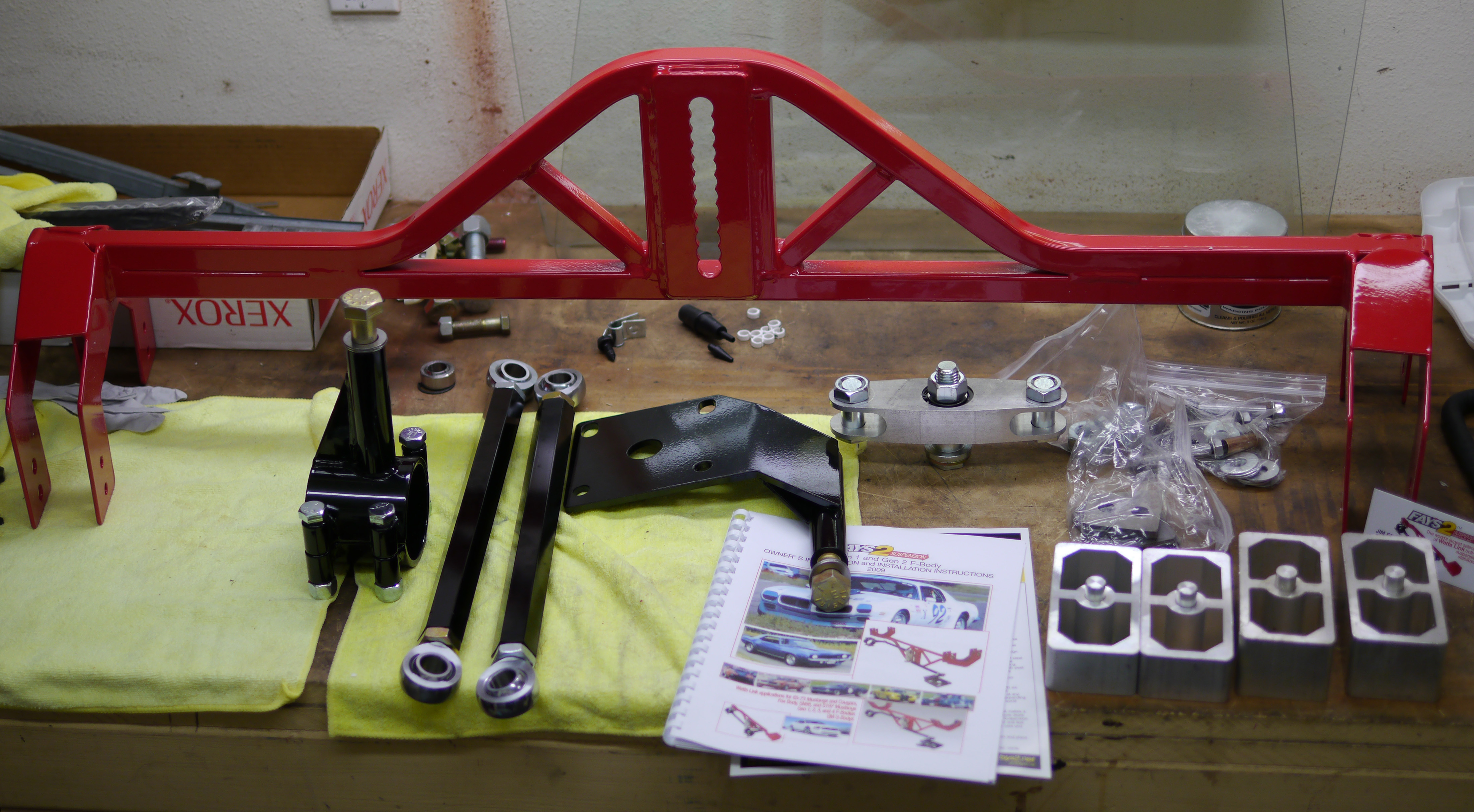
It’s pretty straightforward – the red (only color offered) crossmember piece bolts to the rear frame rails. A central propeller rides in one of the overlapping holes in the center of the unit, allowing ride height adjustability over a ~6″ range, in 1/2″ increments.
Total weight is a little higher than the panhard setup, though fortunately the weight isn’t in a terrible spot (low and rearward) and the crossmember portion should theoretically add some stiffness to the chassis. And of course, it should bring the innate benefits of a Watts over the panhard – elimination of axle lateral movement through suspension travel, and more consistent handling behavior in left and right turns.
###
Since switching from the panhard is going to be a bunch of work – requiring removal of the rear end, cutting away all the nicely welded-on work John did (I’m sure he’ll be laughing at me when he reads this!), and installing the Watts, might as well make a couple other little changes while it’s apart for the umpteenth time.
One plan is to modify the front spring eye bushings – they are mostly as they arrived from Flex-a-Form, and in their provided design, they offer quite a bit of lateral stiffness to the spring, not allowing the end to move at all. This comes at some cost, they also bind the end of the spring a little bit as it looks to rotate in normal suspension travel. With a good lateral locator like a panhard or watts, you no longer need the leaf springs themselves to provide the lateral location. Once could argue you could even go to spherical bearings in the spring eyes, but I won’t be going that far. Will just be trimming the bushings, so they still provide good longitudinal location of the spring eye, so they still transfer drive, brake, and wind-up forces quickly and securely to the chassis, but remove the lateral pieces. This should reduce/eliminate bind in the front, and maybe save an ounce or so!
The other plan is to “adjust” the rear ride height lower. Since the rules disallow changing to coilovers, have to manage ride height through leaf spring spacer blocks.
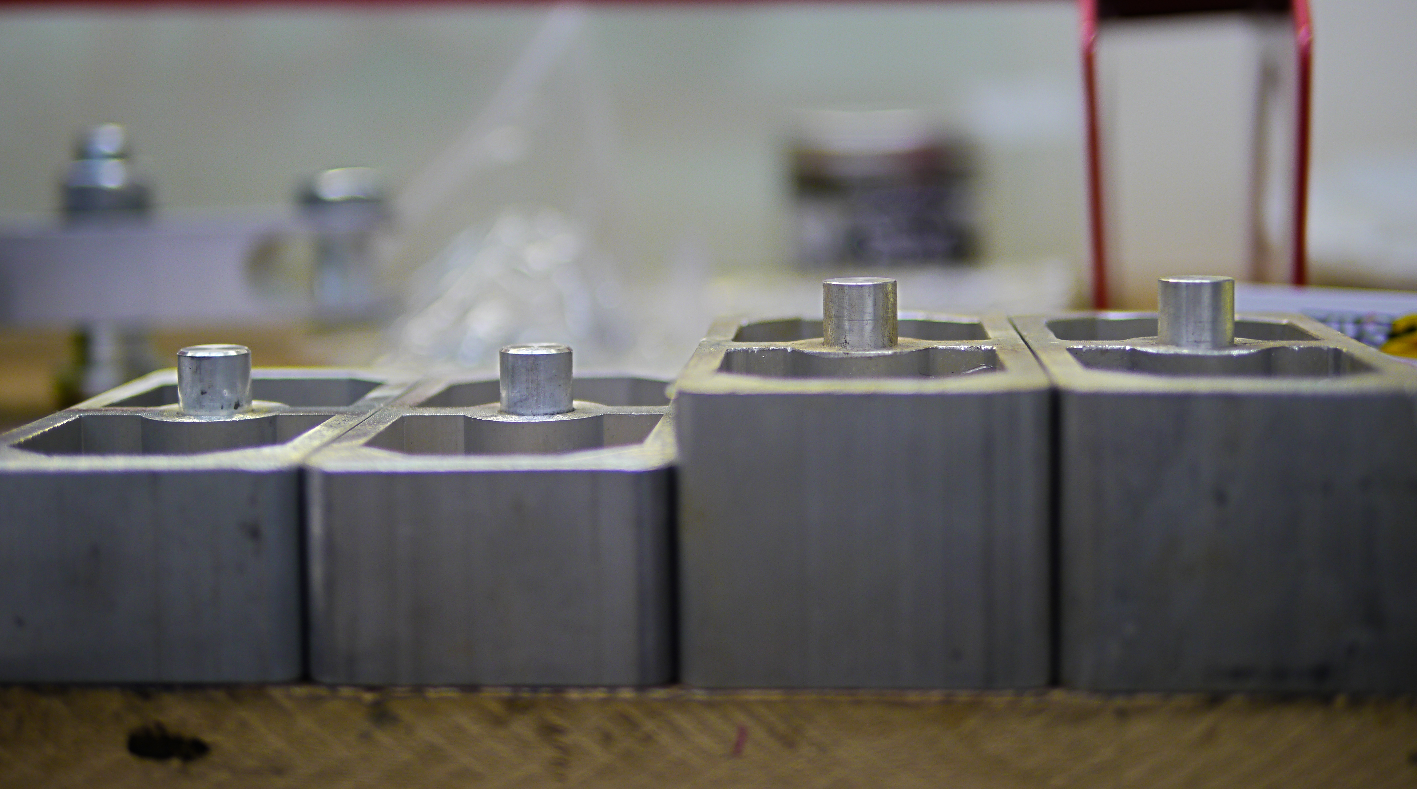
The car has 1″ units on it now – on the left are 1.5″, 2″ on the right. Will be going to the 1.5″ to see how that looks/feels, that way can go up or down a little as needed.
With larger spacers, the axle gets “further away” from the spring, which makes it more difficult for the spring to control axle wrap-up forces under acceleration and braking. I’m hoping the relatively modest grip from street tires, modest rear tire size, and a relatively stiff/thick rear leaf spring, will keep those motions under control.