Turning over some new leafs
Most people think of a leaf spring suspension as a drawback, and in many ways it is, but I also find it one of the more interesting challenges in developing the car.
Unlike a traditional coil sping – which is only responsible for holding up the car – leaf springs are multitaskers, as they control axle location and wind-up, in addition to holding up the car.
The original composite leaf springs for the Camaro had it way too high – might be ok for a stock-height car, at a much-heavier-than-stock rear weight (which my car is not) – so, about 3″ too high, even with a 1″ spacer block.
The next set, what’s on the car now, was better – the lowest ride height Camaro design Flex-a-Form makes. They require only about a 1.5″ spring spacer to get the height correct.
Unfortunately while spacer blocks are an easy way to get ride height where you want it, the more you use, the more they detract from the leaf spring’s ability to control the axle. I already saw in San Diego (and at El Toro for the 1 run where the car was launched with full power) that these leaf springs could not adequately control the axle as installed.
One solution is to install a torque arm system. These are big beefy (Steelitis anyone?) members that rigidly connect to the axle housing, and run forward, up to a crossmember by the transmission, which manage axle wind-up under acceleration and braking. Big, heavy, and difficult to implement legally under ST allowances – things to be avoided if possible.
So instead of a torque arm, trying instead to manage the situation better, with a new set of leaf springs. There’s a couple aspects of spring design that can help.
One is to make them flatter, to enable the use of less spacer block. Since Flex-a-Form had already made their lowest possible ones on their regular Camaro die, they had to try something else, which was the use of a different die, used for transverse Corvette springs. This produced a flatter spring, though in looking at it next to one of the original Hypercoils, am not sure it is flat enough. Will have to get these on the car, to see how much spacer block is needed – hopefully little to none.
The other thing, was I had them make the forward section of the leaf up through the spring mount area, extra thick, while thinning it out in the rear section. The middle and forward section of the spring are the portions most responsible for longitudinal location and managing axle wind-up, so some extra beefiness there should bolster those strengths, while the thinner rear section keeps the overall spring rate in the right range (approx. 250lbs/in. for now).
Watt a pain in the…eye?
Well, that was an awful weekend last weekend.
Thought I’d gotten through all the really gnarly work, but prep for the Watts turned out to be one of the toughest weekends yet, for a few reasons.
One, it was unusually cold in San Diego – not that it ever gets really that cold here, but there was a frost advisory with overnight lows in the 30’s. Enough to make lying on the garage floor feel a bit like lying on a hockey rink…
Two, it was a bit challenging psychologically. With composite leaf springs in the rear, the car has to have some kind of dedicated lateral axle locating device. I set out to cut away a perfectly good one, that somebody had worked really hard on, to do something else that might be only a little bit better. And if I ran into some kind of bad gotcha, that could delay things significantly.
But lastly and most of all – it was the crap! The crap that flew everywhere as I cut away all the metal for the panhard – off the axle, off the chassis. Went through about 15 cutoff wheels on my 4.5″ angle grinder.
It seemed like no matter how I positioned myself under the car, how I set the tool’s guard, and what direction the shower of sparks was flying, it all landed on me. In my face, in my hair, and on several occasions, the searing hot crap seemed to find its way behind my tightly-strapped unvented goggles, right into my eyeballs. On several occasions I had to stop and dig out what landed there. Next time I’ll have better face/eye protection!
John had done a very nice and thorough job ensuring the panhard had a solid base to work from….which means it took a ton of effort to get enough of it out of away, for the Watts to go in cleanly. Once the panhard was out of the way, the Watts was pretty straightforward.
The unit bolts in, consuming the space behind the rear axle, where the factory originally packaged the muffler. (Overall exhaust packaging beyond where it is now, is going to be difficult. Will need to do something more, under-car dumps are kinda ghetto, and the car is a bit too loud still.)
The propeller for the Watts has 12 positions of possible adjustment, comprising roughly a 6″ range of rear roll center heights. Fays2 recommends starting at 4 up from the bottom for “most people”; I started 8 up from the bottom, seeing as my car is 1-2″ lower in the rear than most people run.
They recommend installing the center pivot bolt from the rear of the unit – problem with that, is you can’t fit it in (except maybe on the lowest adjustment hole) with the fuel tank in place. Even if you put it in the car with the bolt already pushed through, you wouldn’t be able to adjust the roll center height later without either pulling the Watts unit, or the fuel tank.
It’s funny too – in the early part of the instructions there is no mention of fuel tank removal, just wheels and normal stuff. But then later around step 8 there’s a “now you can reinstall the fuel tank” line…seems like some selective editing.
Anyway it worked out ok for me – the propeller comes with a number of spacers allowing you to move it forward if needed, and defaults to one. I ended up taking out that one spacer, which puts the center pivot bolt through the Watts frame on the shank of the bolt (instead of the threaded portion), so it should be just as good. And this way I can adjust if needed!
On the driver side, the propeller runs to a new plate sandwiched below the spring and the factory lower spring plate. On the passenger side, it runs to a new axle-clamping tube. With these things, it’s important to get the angles and lengths identical from side to side; otherwise you end up introducing lateral movement, or other weirdness, into the suspension motion. I ended up with link length of 16.5″ and an angle of 9.6 degrees from horizontal, running “downhill” away from the propeller.
Bounced the suspension a whole bunch (easy to do, still no shocks) and there is no perceptible lateral motion or bind in the system. Will be interesting to see how it holds up to the world of autocross!
Watts up with the Camaro?
A long time ago there were some posts on the panhard rod I had built for the Camaro:
http://www.rhoadescamaro.com/build/?p=793
http://www.rhoadescamaro.com/build/?p=866
The reality is, if that had been the last project before the car’s completion, I probably would have gone with it and been perfectly happy.
But lots of time has passed, and I’ve had more time to think about it, and some of the imperfections of the idea chipped away at me.
One thing bugging me, which isn’t the panhard’s fault, is it was tied to this axle with its welded-on components. It hadn’t occurred to me back then, but I’ve since realized, it might be nice to be able to swap out complete rear ends to change final drive ratio. This could be for damage repair, or between venues like autocross and track. By keeping the lateral locator bolt-on, it enables easier swapping between rear ends.
Another, totally my fault, is I probably had John build the panhard rod backwards. The way it was built, mounting to the axle on the left and the chassis on the right, improves grip in left-hand turns, but worsens it in right-hand turns. Totally the right thing to do for circle track, but not necessarily autocross – autocross tends to be fairly neutral in left/right turn distribution, but there are other things about a live-axle car that make it favor left-hand turns (to the detriment of right-handers) and this mounting approach amplifies this disparity. Should have mounted it to chassis on left, axle on right.
The last thing, is I’d always had in the back of my mind, might like to change to a Watts later at some point. The car will be headed into the exhaust shop soon, and I’ve decided it’s better to have the rear in a more final state, for that part of the process. Don’t know if I’ll be able to get the exhaust to exit the rear of the car, but if it can, want to have it do so now, with what is more likely the final rear lateral location solution.
So I bought a Watts. Fortunately this was a pretty easy choice in the aftermarket, there appears to only be one standalone pure bolt-in Watts kit, made by Fays2. Very reasonably priced.
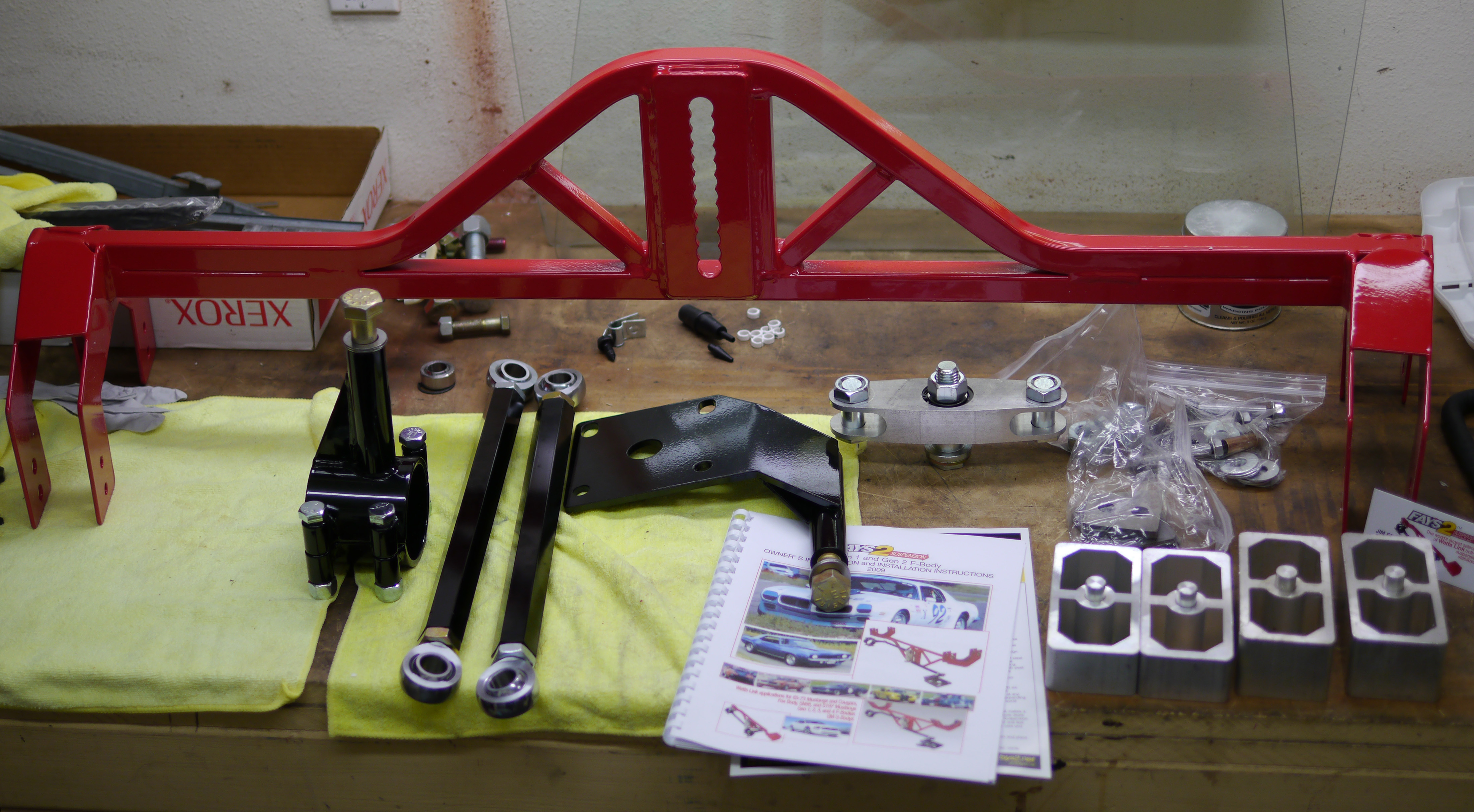
It’s pretty straightforward – the red (only color offered) crossmember piece bolts to the rear frame rails. A central propeller rides in one of the overlapping holes in the center of the unit, allowing ride height adjustability over a ~6″ range, in 1/2″ increments.
Total weight is a little higher than the panhard setup, though fortunately the weight isn’t in a terrible spot (low and rearward) and the crossmember portion should theoretically add some stiffness to the chassis. And of course, it should bring the innate benefits of a Watts over the panhard – elimination of axle lateral movement through suspension travel, and more consistent handling behavior in left and right turns.
###
Since switching from the panhard is going to be a bunch of work – requiring removal of the rear end, cutting away all the nicely welded-on work John did (I’m sure he’ll be laughing at me when he reads this!), and installing the Watts, might as well make a couple other little changes while it’s apart for the umpteenth time.
One plan is to modify the front spring eye bushings – they are mostly as they arrived from Flex-a-Form, and in their provided design, they offer quite a bit of lateral stiffness to the spring, not allowing the end to move at all. This comes at some cost, they also bind the end of the spring a little bit as it looks to rotate in normal suspension travel. With a good lateral locator like a panhard or watts, you no longer need the leaf springs themselves to provide the lateral location. Once could argue you could even go to spherical bearings in the spring eyes, but I won’t be going that far. Will just be trimming the bushings, so they still provide good longitudinal location of the spring eye, so they still transfer drive, brake, and wind-up forces quickly and securely to the chassis, but remove the lateral pieces. This should reduce/eliminate bind in the front, and maybe save an ounce or so!
The other plan is to “adjust” the rear ride height lower. Since the rules disallow changing to coilovers, have to manage ride height through leaf spring spacer blocks.
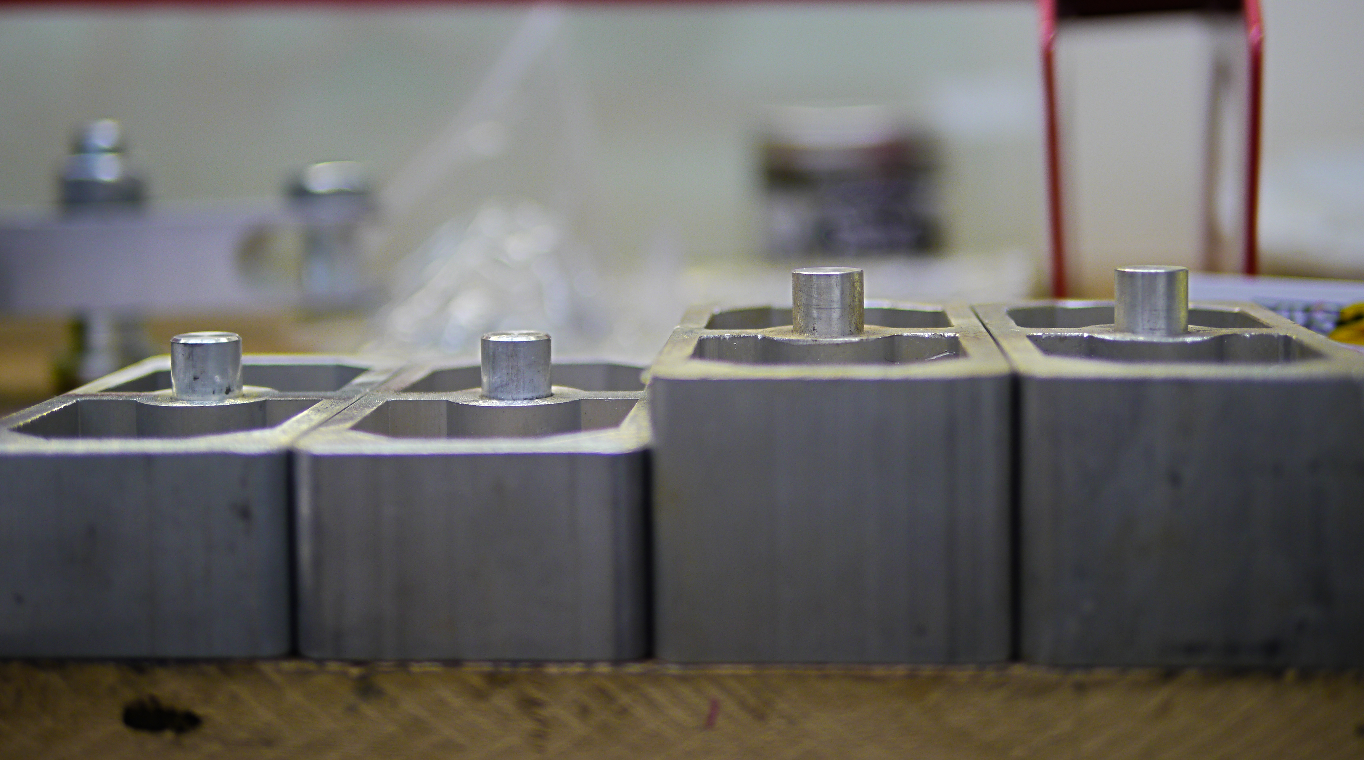
The car has 1″ units on it now – on the left are 1.5″, 2″ on the right. Will be going to the 1.5″ to see how that looks/feels, that way can go up or down a little as needed.
With larger spacers, the axle gets “further away” from the spring, which makes it more difficult for the spring to control axle wrap-up forces under acceleration and braking. I’m hoping the relatively modest grip from street tires, modest rear tire size, and a relatively stiff/thick rear leaf spring, will keep those motions under control.
Headers back, couple minor things
Headers made it back from Swaintech with their White Lightning coating.

Again a very high quality result, and now that I see how close the headers run to critical components like the starter and power steering, am even more glad I went with it.
The coating itself should last a long long time, and help the neighboring components last longer too.

Thought I’d let the pimpy valve covers make their entry now. They’re the same off-white used everywhere else on the car, though they do look a little different here in the light.
Still have a few little things to take care of on the underside of the car before the exhaust can go in, not the least of which is the remaining bends to make on the shifter linkage so it doesn’t bind itself up when in reverse.
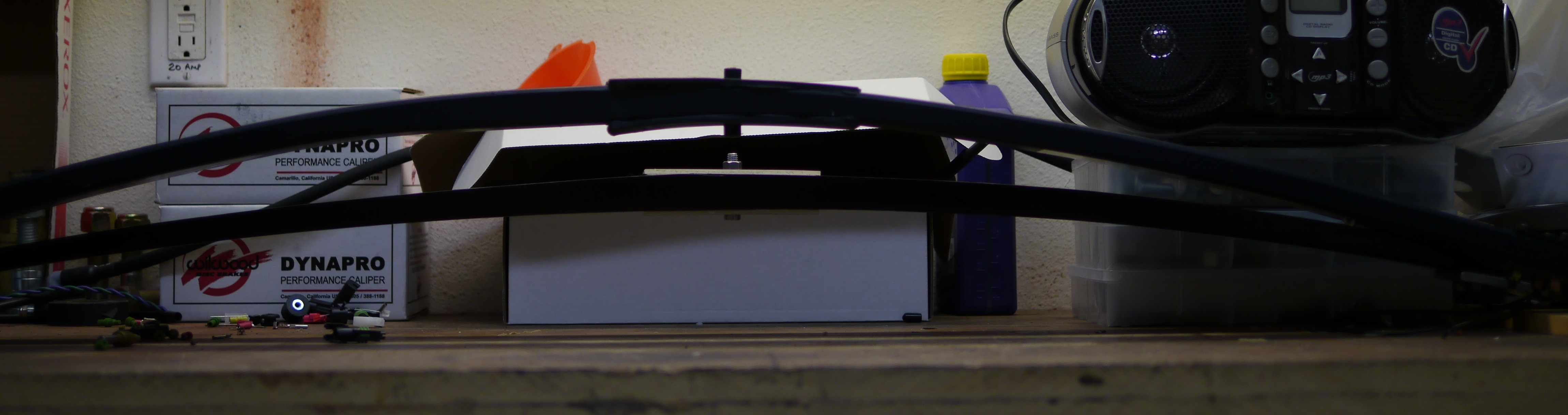
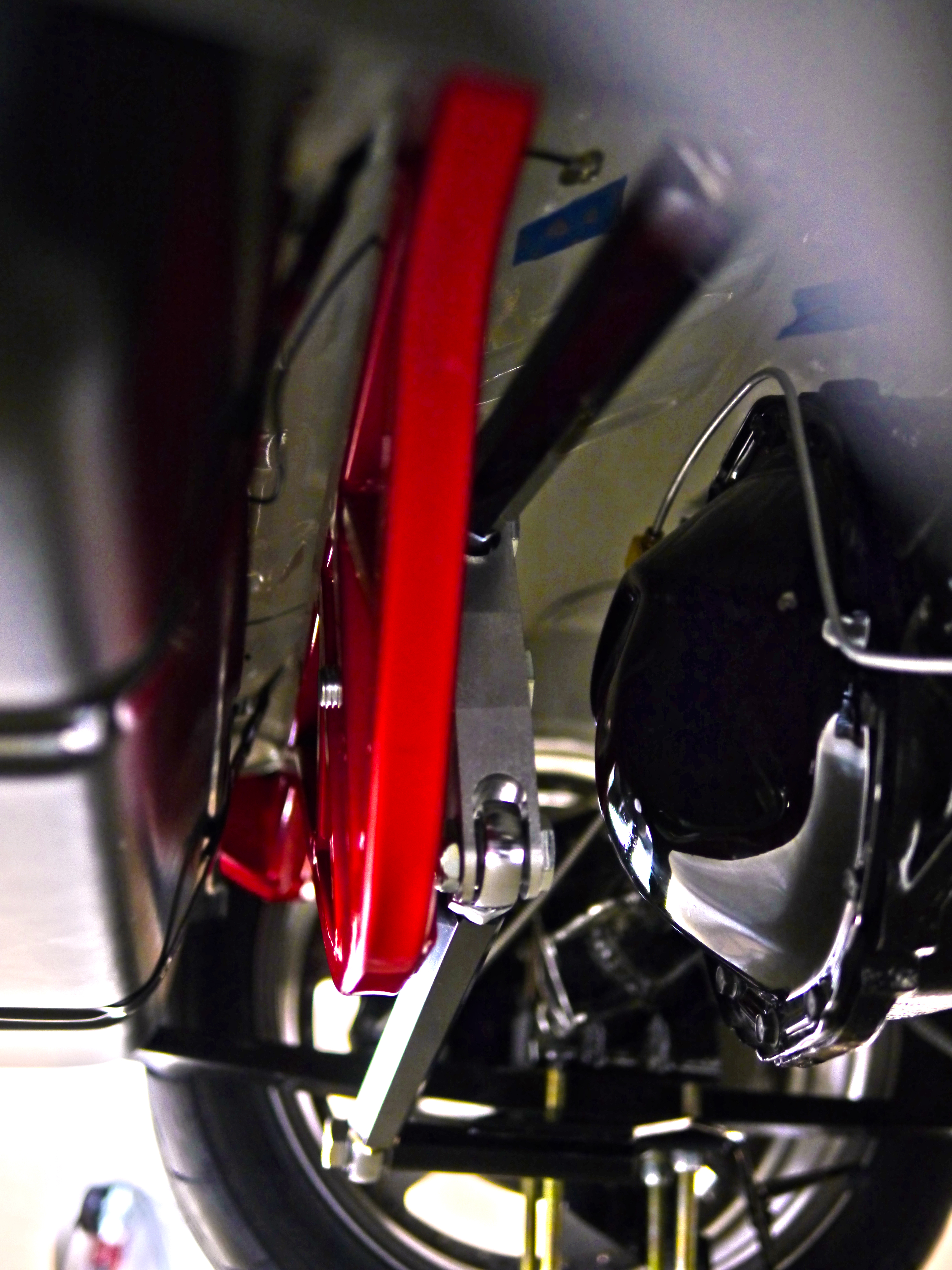
Out back, made a couple modifications to the rear swaybar, even though it hasn’t been used yet. One, was shortening the endlinks on both sides by about an inch. The second, was shortening the driver-side arm, so it’s the same length as the non-adjustable passenger side. These two changes should provide a lot more bump travel – with this arm length, the bar arm ends will contact the floor (if nothing else hits first) at its highest point, allowing for maximum travel. You can see it somewhat here:

A couple weeks ago I put together a to-do list of things I could think of off the top of my head. Presently it has 57 items, of which 7 have been done. 4 will require outside help – mount tires to wheels (which themselves haven’t even been made yet), add a slight bend to front swaybar arms (purchased a narrower front center section for the swaybar to allow for more tire clearance, but it requires modification to the arm shape), welding the alternator bracket to the header (found a bracket but should have it welded for better stability/reliability), and the headliner install. I could *try* the headliner install myself but everything I’ve seen says you need at least 2 people, if not 3. It’s not like newer stuff where it snaps in, it’s a real fabric thing with adhesive and these wacky metal rods. Looks like awful work.
Each of the tasks on the list are 4-8 hours, so still a long way to go. Will try to take more pictures along the way. Here’s an artsy one in the meantime…

Rear axle lateral locator complete
So you’d think with nearly complete freedom to design and implement a top-notch lateral locating device for this live axle car, one would choose a Watts link right? After all, a Watts offers perfect symmetry when turning left and right, and doesn’t move the axle laterally as the suspension moves through its range of travel.
Along those lines, the first big question for anybody implementing a Watts link, is whether to make the main pivot point chassis mounted, or axle mounted. Axle mounted (image courtesy Griggs Racing):

Chassis mounted (image courtesy Fays2):

There’s a couple imperfections with the Watts however. The first pertains to the above choice. If you choose the axle-mounted center pivot, then you get the “advantage” of a consistent roll center height. But half the world will tell you you’re an idiot, because the sprung mass of the car moves in squat and pitch, so the “lever arm” from the roll center to the center of gravity, changes during squat and pitch, dynamically altering the rear roll couple. Plus it’s harder to adjust.
So you can instead choose the chassis-mounted pivot. This keeps the roll couple more consistent as the car pitches and squats. But now you’ve got to build a big heavy structure to support the center pivot, plus…wait a second, maybe the roll couple changes from the diff-mounted center pivot (loose on entry, tight on exit) could be beneficial? By now the other half of the world thinks you’re an idiot for having done a chassis-mount Watts.
We won’t even talk about a Mumford link, which might be cool if you’re scratch designing a live-axle chassis, but on something like the Camaro it would take 40+lbs. of structure welded into the rear to support it.
In keeping with the style of a person building a 44 year old car for a Street Touring class, I’ve made the choice that lets everybody (not just half) think I’m an idiot – a panhard rod.

Now, we all know the downside of the panhard – it moves the axle laterally as the suspension moves. The shorter the panhard, the more movement. The panhard bar on the car now is about 34″ long, which is as long as it could be made when considering the packaging restraints of the leaf springs. Another mitigating factor is, as with the front, by keeping the rear suspension stiff, I’ll be able to minimize the vertical (and thus lateral) movement of the rear axle. At 2″ of travel (pretty much all it will get), the axle will shift laterally by only .06″, about 1/16″. This is not a completely negligible amount, but I plan to run tall-ish sidewall rear tires, which will mask much of this, and we see tires move around on their wheels by 1/2″ or more while under heavy load.
The other maligned characteristic of a panhard rods vs. Watts, is their asymmetry in handling. The roll center, usually defined as the bar’s midpoint, rises or falls based on which way you’re turning, and which way you have it mounted. This will always create a difference in the way the car behaves turning left vs. right. Even if you start with the bar horizontal at resting height, as the car rolls, the lateral forces fed through the now-non-horizontal bar will serve to load the rear axle differently depending on which way you turn.
On the surface this may seem like a bad thing, but it can be used to counteract other asymmetries. For instance, in a live axle rear car, on hard acceleration, driveshaft torque is going to tend to weight the driver’s rear tire, and unload the passenger rear tire – that’s why you always see drag racers mounting their battery in the right rear, and why live-axle cars usually have such a bad time putting down power out of right-hand turns. This car is going to be making good power with good gearing so when good grip is available, this asymmetrical loading can become very significant.
We can use the panhard to counteract this asymmetry somewhat, by mounting it to the left half of the axle, and to the chassis on the right. This puts the panhard in compression, when in a right-hand corner. That compression is going to help better load the rear axle in right-hand turns, counteracting some of the axle’s natural asymmetry.
And actually, there’s a lot that’s asymmetrical about any race track, and any Solo2 course – both are either clockwise or counter-clockwise (ProSolo, with its mirrored courses, is the exception). The panhard rod is unique in that it allows one to adjust-in some inherent asymmetry, that may help if a particular event features a strong abundance of key turns in one direction or the other. It’s also lighter and less complex than the other options.
My panhard bar is simple but should be very effective. The sawtooth axle-end adjuster and screw-type chassis-side adjuster supply an essentially infinite number of discrete adjustment postions, as opposed to the 4-5 “holes” most solutions offer.

The solution overall is only about 16 pounds, a good bit lighter than the Watts options I’ve seen out there. Only about 6 pounds of it is unsprung weight, and the axle-side mount (all unsprung) will be lightened a bit – it’s designed to be bolt-on to the axle, but by welding it on, can eliminate the weight of the bolts and some other unneeded structure, while actually making it stronger.

The rear suspension still isn’t done from a fabrication perspective, though it’s getting close. Where’s my rear sway bar? Still that to do, soon thereafter should see some progress on the front. There’s one or two goodies visible in the pics above, I’ll let people chew on them for a while before discussing them further…
Agricultural 12-bolt and down the rabbit hole
Some of the parts needed for this build are getting harder to find, this is one of them.
The GM 12-bolt is an extremely robust rear-end with an 8.875″ ring gear. It is often compared to the ubiquitous 9″ Ford rearend, the GM piece being a tiny bit less stout, but more efficient (less driveline hp loss).
I’ve been looking for one for a while, and one turned up on Craigslist. The price was good, picked it up Friday.
It is a correct ’67-built Camaro piece. According to the owner, it had been sitting in storage for about 20 years, and then in his yard for the past several months. Based on the dirt removed, by several months, he might have meant 120 months!

Inside the brake drums, an entire ecosystem was flourishing, all sort of spiders and insect carcasses abounded. In this pic you can see the huge black spider that “owned” the passenger side drum-

I don’t think I should count all that dirt as weight reduction, pretty sure it wasn’t there from the factory 🙂

Getting this thing in shape is going to be a bit of work.
My plan was/is to get the car minimally prepped, so I could take it to a welder and have all the big on-car welding projects done. I have taken a welding class, and have access to a good MIG, but don’t trust myself to weld anything critical, like a live axle lateral suspension locator.
The lateral locating device will be attached to the rear axle, so the axle needs to be clean and ready for welding. I also wish to package the device towards the end(s) of the axle. The limit of how far towards the end the device can be located will be defined by the brakes. Hmmmm…down the rabbit hole we go………..
So it looks like maybe I should get the rear brakes put together to ensure I don’t get welded into a packaging dead-end. Now, STX does have a “big brake kit” allowance. Unfortunately, like many of the ST category’s allowances, it is a rather Fisher-Price allowance (“My First BBK”). I can say that, having spent a few years on the STAC – aka the Street Touring Advisory Committee, the “subject matter expert” rules making/advising group for the ST category. I get what they had in mind – the blingy cross-drilled stuff you see in the tuner magazines that are easy bolt-ons for popular cars. Nothing exotic, no messing with the hydraulic system, nothing requiring any engineering on the part of the ST car builder, just bolt-on kit/kid stuff.
Now, there are plenty of “bolt on” kits for the first-gen Camaro. However, none of them are really designed to work with the factory master cylinder, which is rather large (1.125″ bore). Those kits all come with some kind of late-model Camaro or Corvette master cylinder, often with a proportioning valve.
Can’t change the master cylinder, can’t change the booster, can’t add a proportioning valve – at least, not in the classic fashion. Some first-gen Camaros came with a proportioning valve, but that was only the heavier cars with A/C, not the Z28, and even if it did, I couldn’t change it.
The flexible brake lines I can change, the calipers and bracketry I can change, and I can use any rotor equal to or larger than the diameter of the factory rotor or drum. Even the smallest aftermarket stuff is about 12″ (stock drums are 9.5″) so the diameter won’t be an issue. Since the calipers themselves are free, I was thinking I could use one small proportioning valve right at the inlet to each rear caliper. Then I could say it is part of the caliper and thus legal. I expect to receive emails from people saying “hey, that’s not what they had in mind” shortly 🙂
But I’m not totally sure I even want to have a proportioning valve. The Viper had one when I bought it. I ran it that way for a couple events (nothing National, folks). The car from the factory had shorter front tires than rears, and the previous owner raced it with equal sized tires all around. Taking the car back to Stock, I removed the valve as it wasn’t legal, or needed. When the Viper was on the ideal f/r diameter tires, I thought its brakes were the best of any car I’ve ever driven, and a lot of that was the factory blessing the car with a healthy amount of rear bias. When I ran a slightly (.6″) taller front tire, it would try to kill the driver with too much rear bias. So, suffice it to say, there isn’t a ton of room for error in sizing the brake system, but the proportioning valve does give you a bit more leeway.
I won’t go too far into designing a brake system here, but there are several key variables to consider. In my case, some are fixed, some I know or can estimate, and some are free to change.
Fixed:
Master cylinder bore
Brake pedal ratio
Brake booster ratio
Proportioning
Known/estimated:
Static front weight
Static rear weight
Wheelbase
CG height
Maximum deceleration (use this to calc load on front and rear tires at max decel)
Front and rear tire diameter
Free:
Rotor diameter
Caliper piston area
…from all this there’s a bit of thinking to do. You can design a perfect system on paper, but if the parts don’t exist out there in the world, it doesn’t do much good. Not going to have custom calipers made for this. Have to see what is available from Wilwood, Baer, Brembo, Stoptech, etc., and piece together a working system from their available components. Also have to consider – is the car going to get track time? Autocross puts much less demand on brakes than does the track. Most of my track experience is in the S2000, which had somewhat undersized and undercooled brakes, a constant problem.
If the car isn’t going to see much hot lapping, then 12″ rotors will probably be fine. If it is going to be tracked hard, I’d probably want 14″ rotors, as I plan to run only 18″ wheels, and they’d provide the ultimate in thermal capacity. The bigger rotors are heavier though, a disadvantage at autocross. 13″ rotors might be a good compromise. The larger diameter rotors also provide more brake torque with all else equal.
Speaking of weight, the stock rear drum brakes weighed 43 pounds between the two sides. In my STX Z28 spreadsheet, was anticipating losing 7 pounds in rear brakes, would like to stick to that if possible. Also have to retain some kind of parking brake, which adds weight.
Browsing Wilwood’s brake kit chooser site:
http://www.wilwood.com/BrakeKits/BrakeKitApp.aspx
They ask about the axle offset. Hmm. Didn’t have the axle apart enough last night to get this measurement, and even if I did, am I sure it would be right? I’ll be changing the limited slip, and didn’t know if the axles in there were the stock size and length. So one more trip down the rabbit hole, might as well get my limited slip now, with OEM replacement axles (no donuts here Civic guys! ;)), so I can put all that stuff together and measure my axle offset properly. Will need the measurement to be final and exact regardless of whether or not Wilwood stuff is chosen. They list three sizes, 2.75, 2.81, 2.91. Again, not much room for error here!
Will go into a discussion about the limited slip choice later. One somewhat unfortunate thing, is the GM 12-bolt isn’t the hottest diff out there, so it doesn’t have all the fancy choices some other cars get. I’ve had excellent experiences with ATS/Carbonetic in the IS300 and 240SX, and the OS Giken has gained huge popularity in autocross circles as of late. Still, there are some tried-and-true options for this car I think I can make work fine.
So I got things a bit further along today. Didn’t try measuring the axle offset, figured the bug guts might throw it off by .06″ anyway.. 🙂

Whole thing covered in funk and some kind of white paint, got most of it off. As bad as it looked on the outside, the insides look great. Everything very straight and true, turning very smoothly. It had a 3.07 open diff in it, so it’s not likely to have seen much heavy use. The gears all looked better than any of the Viper diffs I’d worked on!
Oh, and speaking of gears, one cool thing about old cars, is you had LOTS of choices-
http://camaros.org/drivetrain.shtml#AxleCodes
…and the Z28 could be ordered from the factory (unlike the dealer-installed cowl-induction or header options) with just about any of them. 3.73 standard. These days, you have to order a whole big option package or something to get a different rear ratio, you never get to choose it individually.