Exhaust work and dyno session
Street Touring rules allow for headers but we must retain catalytic converters no further than 6″ down the flow path from the stock unit. In the previous post detailing header install the Berk high-flow cats (which sit in roughly the stock place but are much shorter in length) went bye-bye.
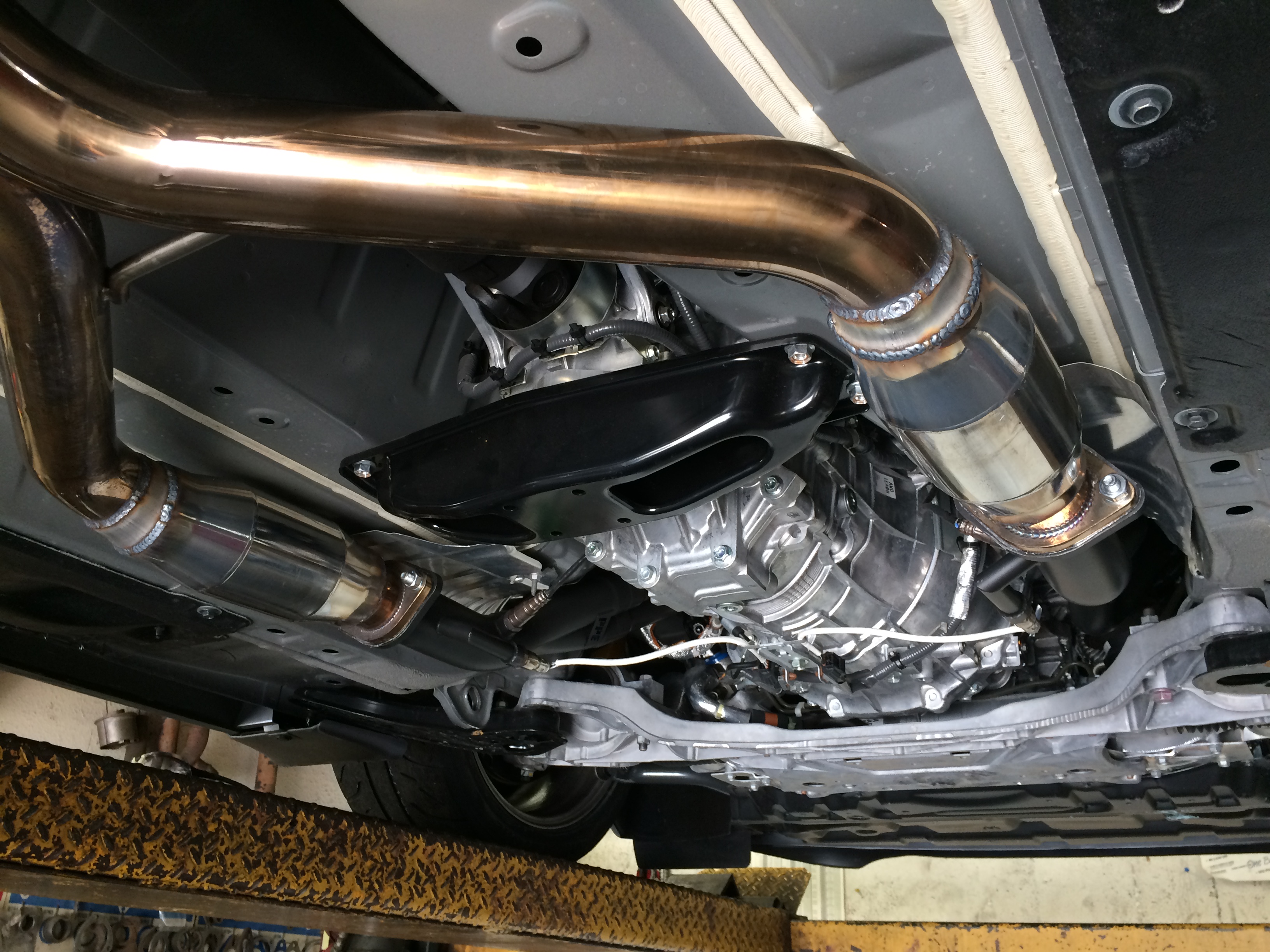
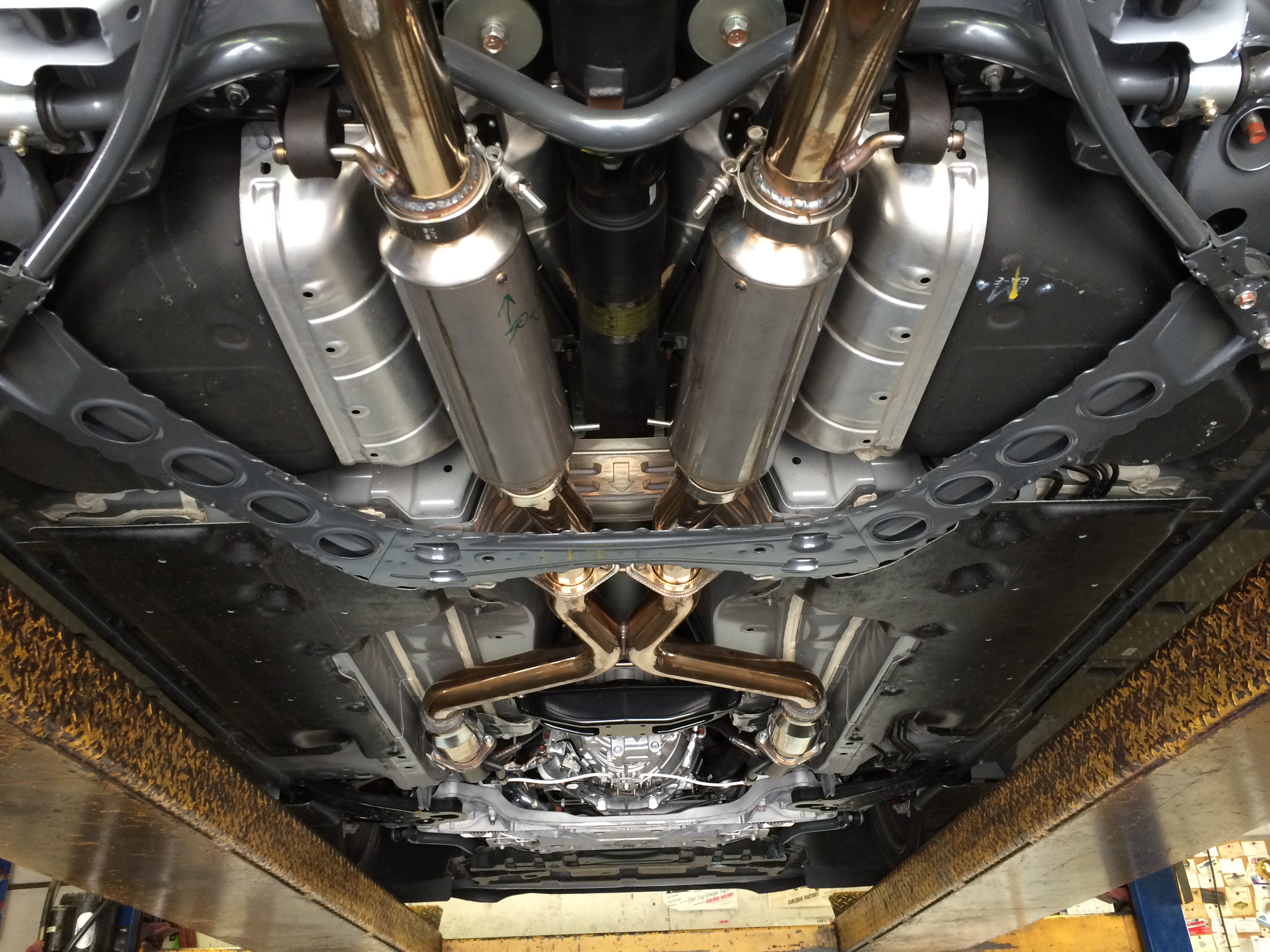
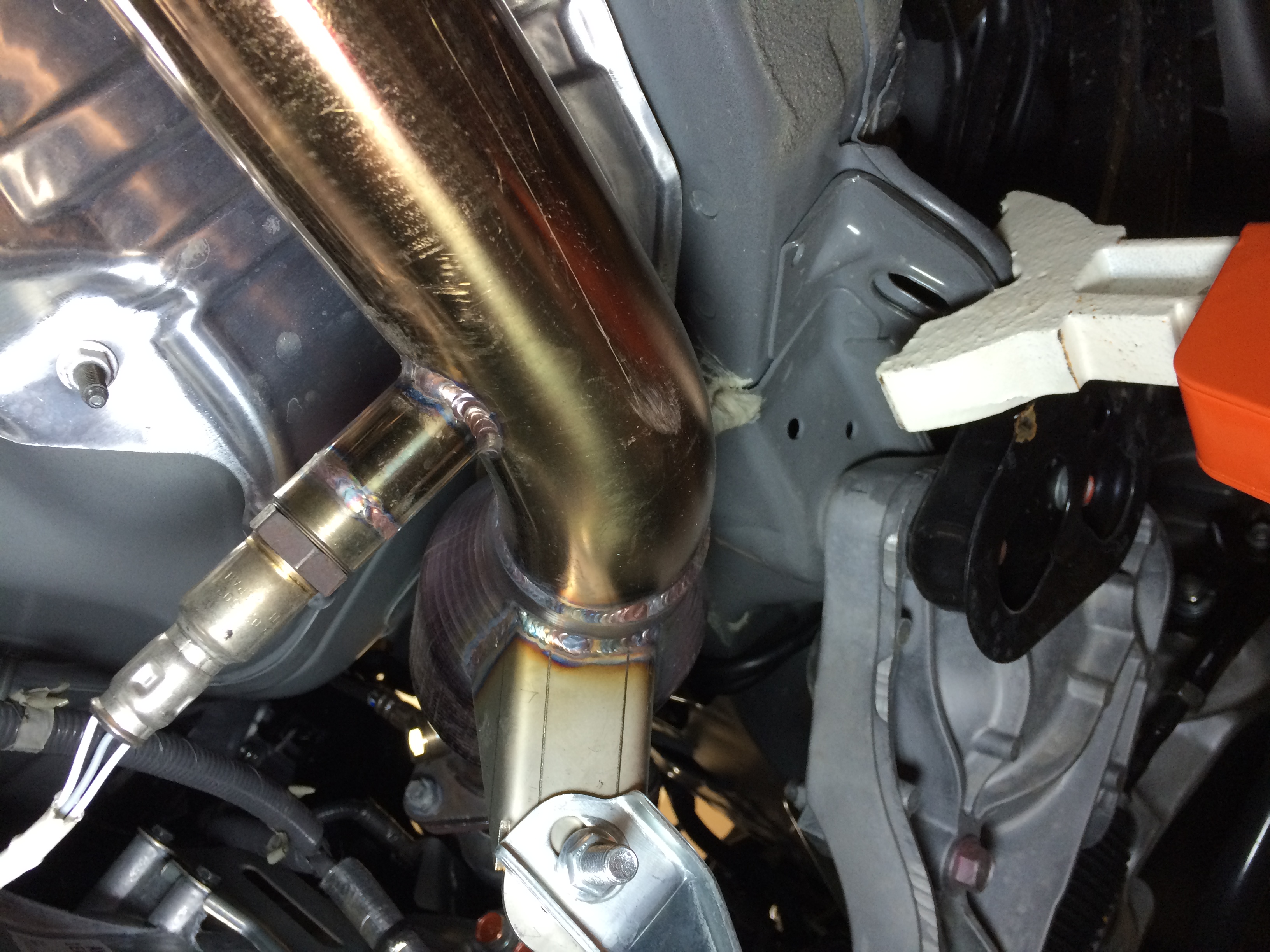
Spent the morning at A&A muffler here in town (and recommend them if you need exhaust work done in San Diego) – first project was to get a new pair of high flow cats welded in just aft of the new longtubes, where the garageline mid-pipe provided a flex joint. These cats are 100cpi high-flow units from my buddy Rick at Ciro Racing. Given how far back they are, and how large and not dense their cell structure, they should be providing very little backpressure.
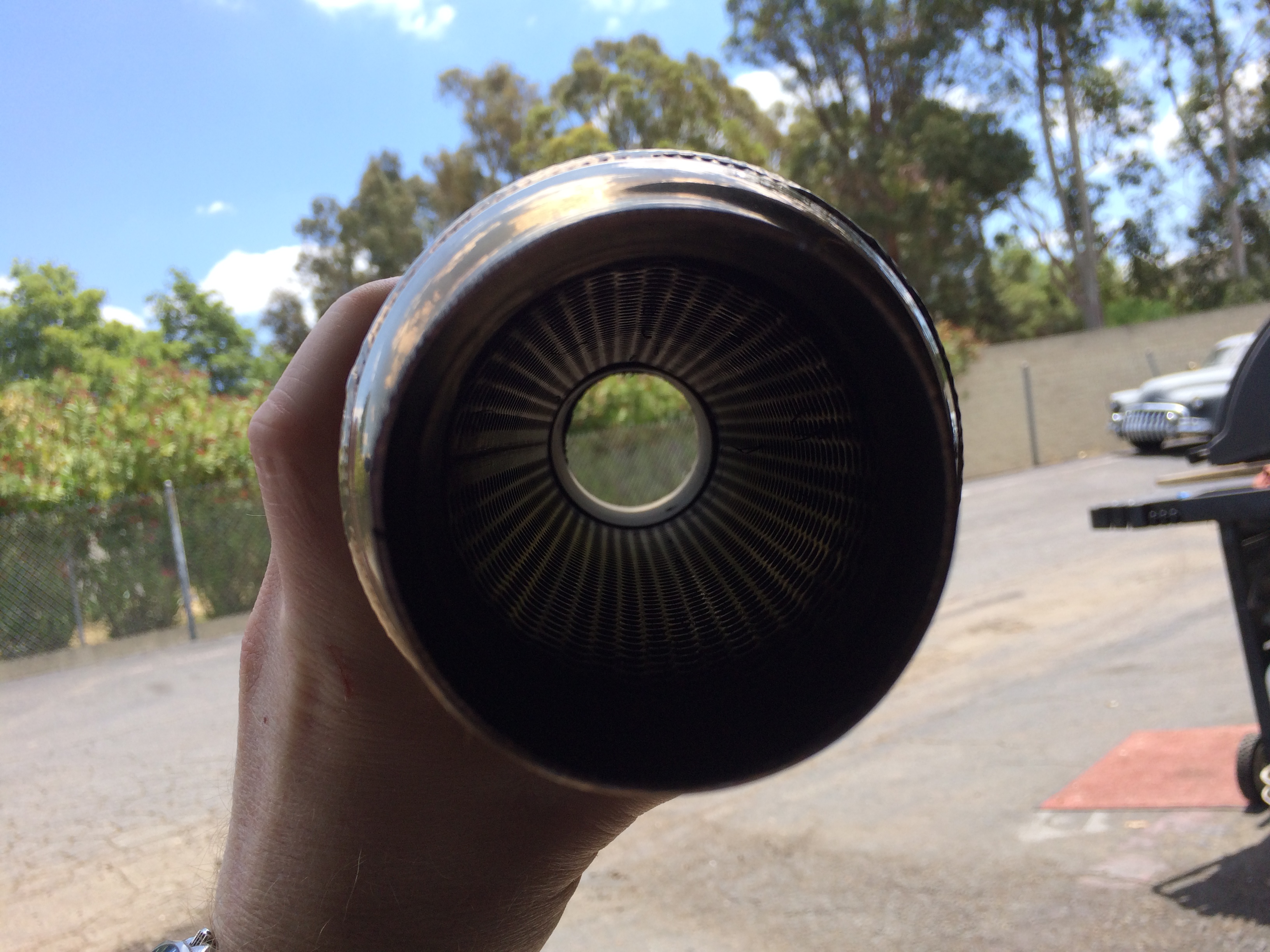
From there it was back to where garageline provided a pair of resonators. They have a ~10″ body length and help knock the noise down a little – but there’s room for more. The garageline midpipe provided a great canvas for the next evolution of the car’s exhaust.
Inside view of one of the resonators removed:
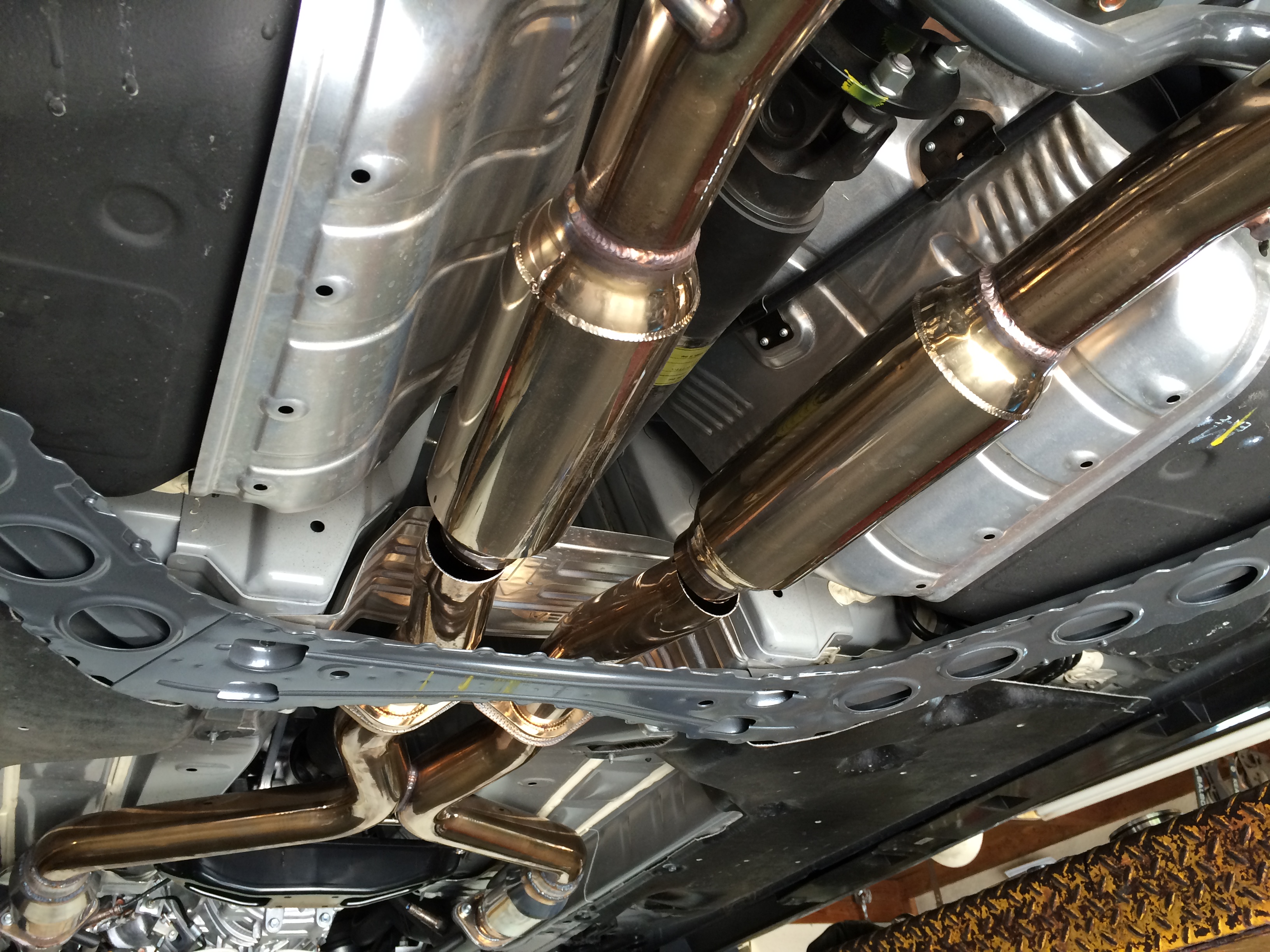
In their place, a pair of 2.5″ 17″ long Burns Stainless single-stage mufflers. Very lightweight but also very effective. Installed with v-bands to they can be swapped out for straight pipes later if needed. These mufflers *shouldn’t* cost much if any power but I didn’t back-to-back with straight pipes. I don’t think they’re any more restrictive than the resonators that were in there already.
The car is actually a little quieter now than it was before with stock manifolds, the Berks, and the unmolested garageline midpipe (kept the stock muffler on throughout). Hit 95db in San Diego with that setup – hopefully this gets it under, hard to say.
From there, 100 miles north for a dyno touch-up at Shawn Church’s in LA. This is probably maxing out the iPhone microphone, but believe it or now, was a noticeably a little quieter than last time.
Here’s how she did:
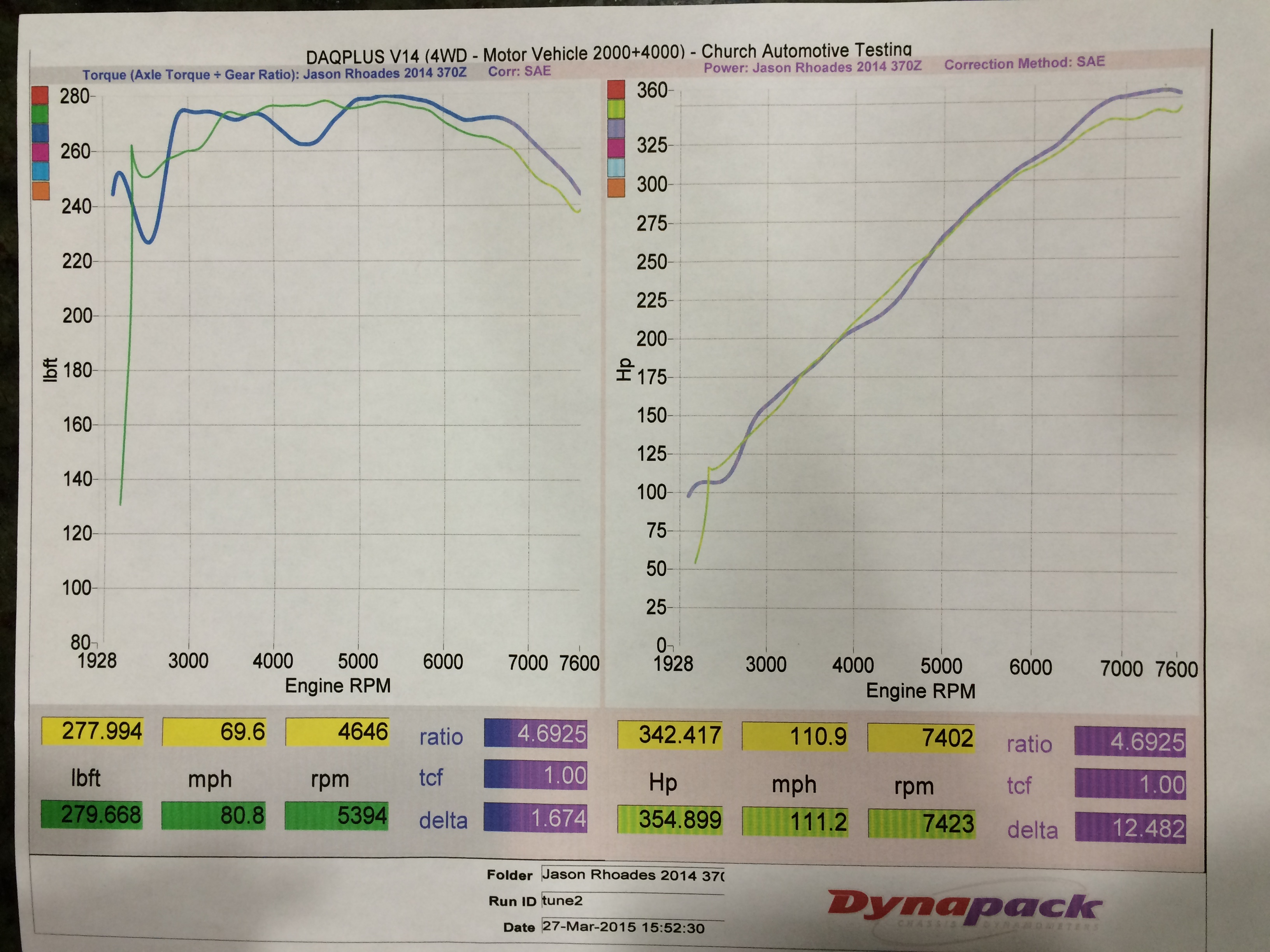
The bummer point first – there’s a new 1000rpm-wide torque dip centered around 4400rpm. I don’t know that I’ve seen this before on other Z’s with longtubes – need to keep looking. I suppose it’s possible it’s some artifact of either the new cats or mufflers, but it’s so pronounced, hard to say. It was actually worse than this on the first couple tunes, this is the result with the dip minimized via tuning.
Two good areas more than make up for it. First is the far left, from ~2800-3500rpm – those are some real gains, something like 15ft-lbs. in places. With the car’s gearing it does ~8.8mph per 1000rpm, so our slowest corners (~25mph) work out to about 2850rpm.
The car is stronger once out of the dip all the way to redline, especially above 6000. It doesn’t seem as coarse and choked as it did from the factory, now it zings all the way to the top. Makes the car a lot more fun to wring out, with the sounds it made stock, it sounded like you were hurting it, now it seems to love to rev 🙂
The sound is a little bit “buzzy”, not sure how else to describe it. You can kinda hear it in the video. 370 folks who switch to high-flow cats hear a buzz on decel through certain parts of the rev range – the car now does that everywhere. There’s a bit of vibration through the pedal at 3500rpm under heavy throttle but nothing terrible. Glad I kept the stock motor and trans mounts!
Last thought on another benefit – the headers saved 10 pounds over the stock manifolds + Berk HFC.
PPE Long-Tube Header install
This is one of the more gnarly projects for these cars. Headers, particularly long-tubes, can be tricky to install on any car but it’s especially the case with the 370.
I’ve read a few stories of people working through it, but haven’t seen the journey well documented yet. Tried to take a lot of photos and mental notes along the way.
By myself using jackstands, it took me about 12 hours to do it over 5 evenings. I work pretty slowly and made some oopsies along the way, but at the same time my car only has 1400 miles and I didn’t have any issues with stripped/rusted/seized fasteners. I’ve seen people pay anywhere from $600-1000 to shops to do the install – point being, have a good idea of what your own time is worth to you before beginning.
1: get the car in the air
2: remove factory strut bar. You don’t have to remove all the panels at rear, just the middle portion. Nuts and bolts are 14mm
Step 3: View of the driver’s side heat shield. Held in with 4x 10mm bolts. Got to all of them from above.
4: View of the passenger heat shield. Same thing, 4x10mm bolts accessed from above. Both heat shields come out up/forward.
5: Time to get underneath the car. There are about 8,000 10mm/phillips bolts holding in the undertray, with three of the push-snaps in the middle. Easiest to remove all the bolts and the snaps last so it isn’t hitting you in the face half the time.
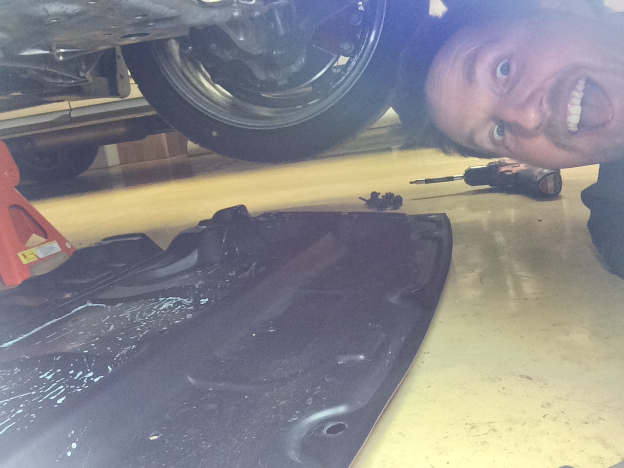
Better be still smiling here, if not you better turn back!
6: Before shot of the cats. Car already has Berk HFC on it, but the stock would look similar here.
7: Passenger cat “before”. Cat removal/replacement is covered in HFC install DIY articles. Some people have removed the OE headers keeping the cats attached, and I suppose you could. The Berks came back off pretty easily.
8: Driver’s side “before”. Little bit busier in there 🙂
9: Passenger cat out. With the HFC you can get to all three fasteners from underneath which is nice, no crazy 3′ snake of extenders like you have to do when removing the OE cats.
10: Driver’s side out. Only a little tougher than passenger.
The above took me about 2 hours, that was evening 1.
Evening 2 begin:
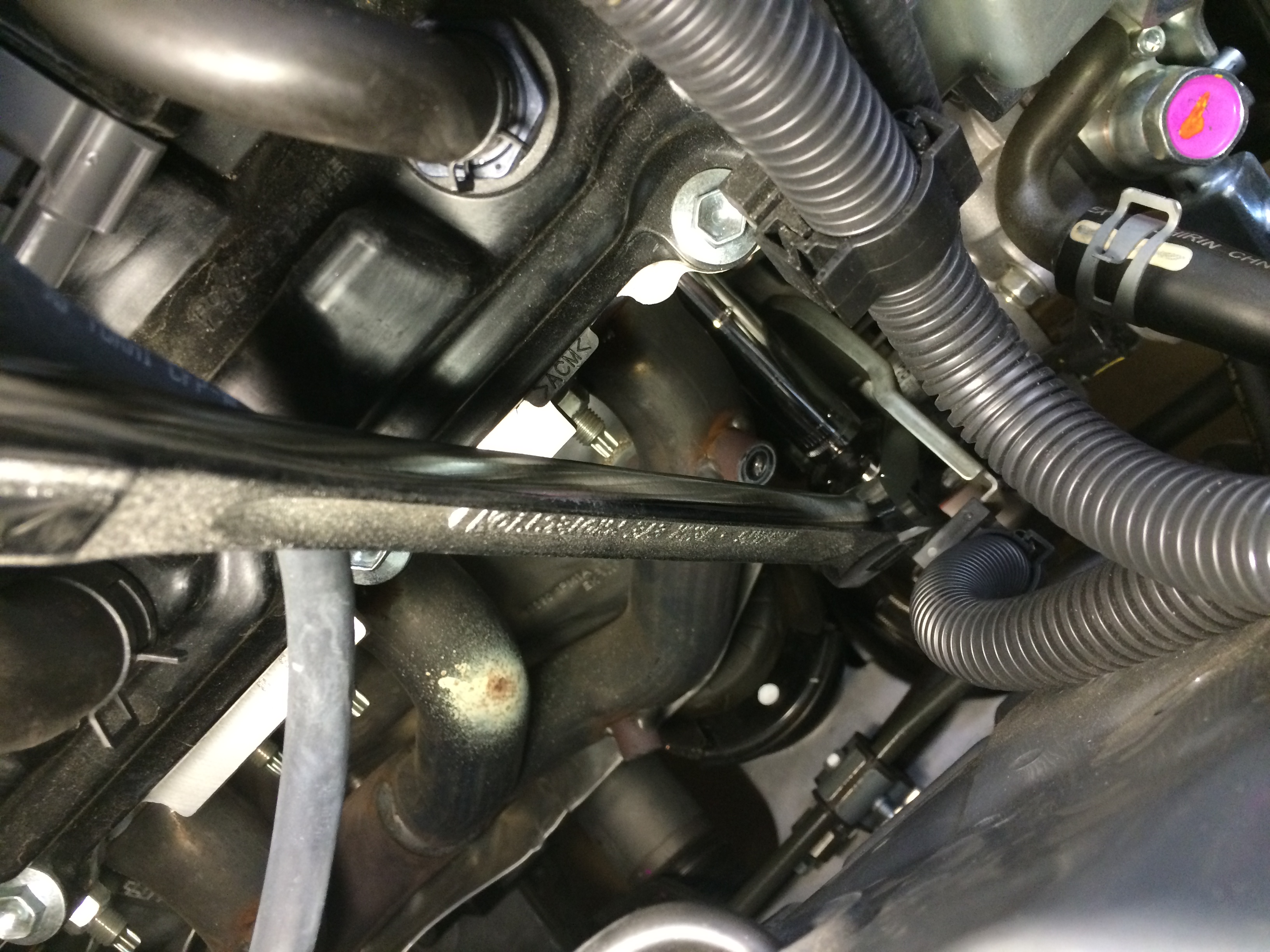
11: View of the passenger header before removal. Both sides are held in with 6 nuts on studs. The studs are diagonally opposed across each cylinder’s exhaust port.
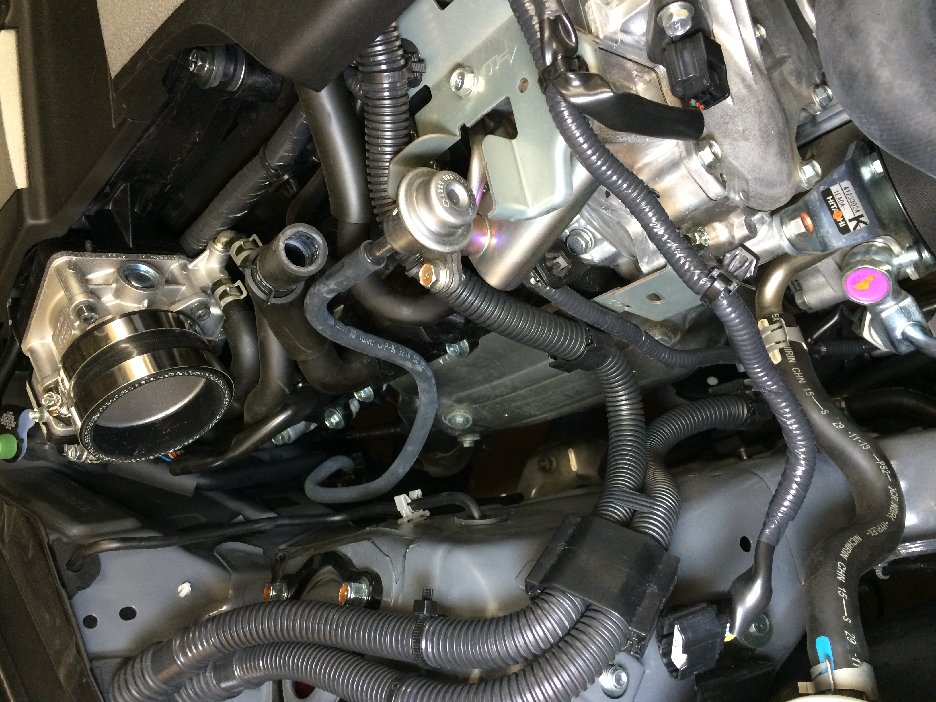
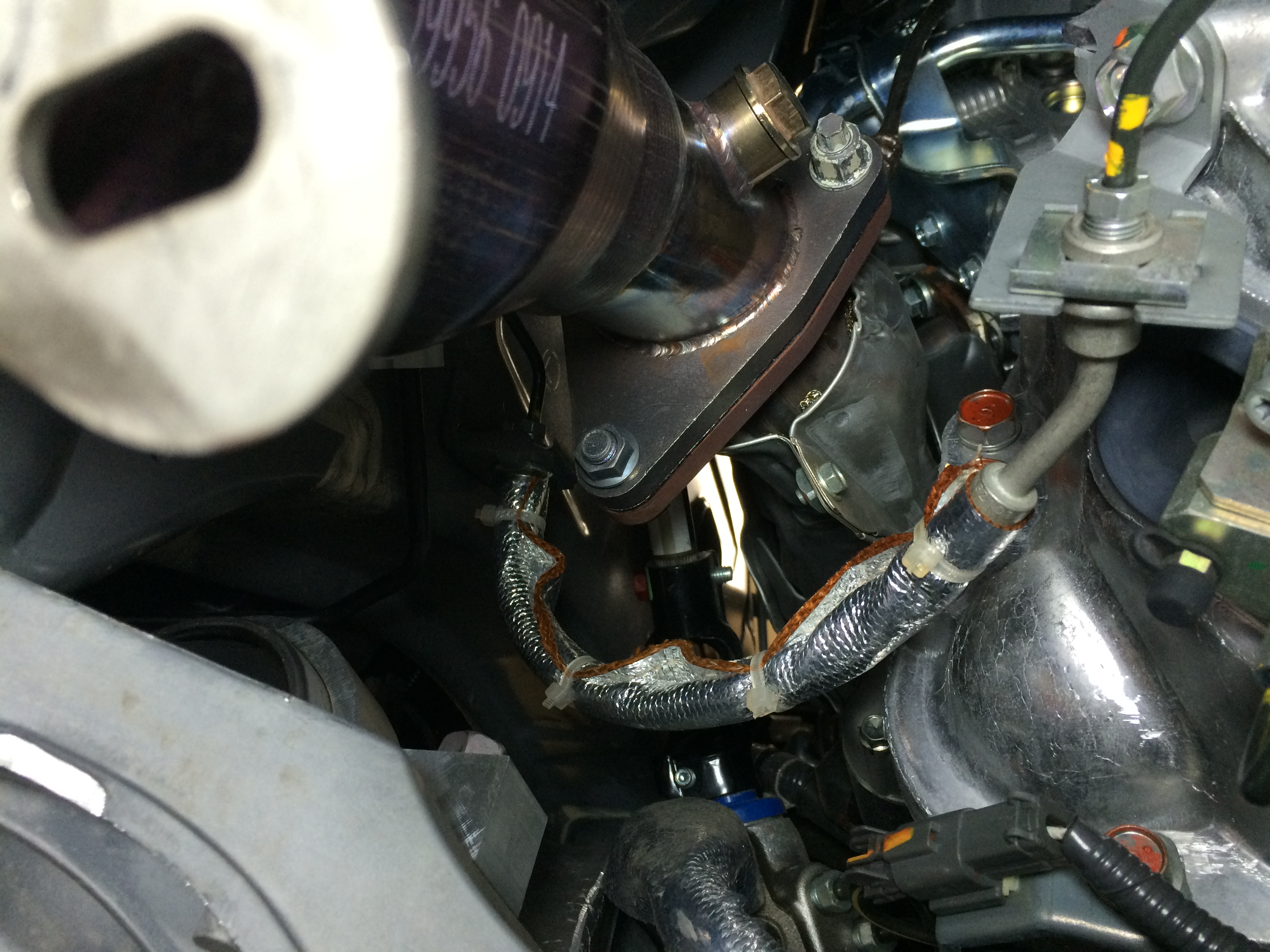
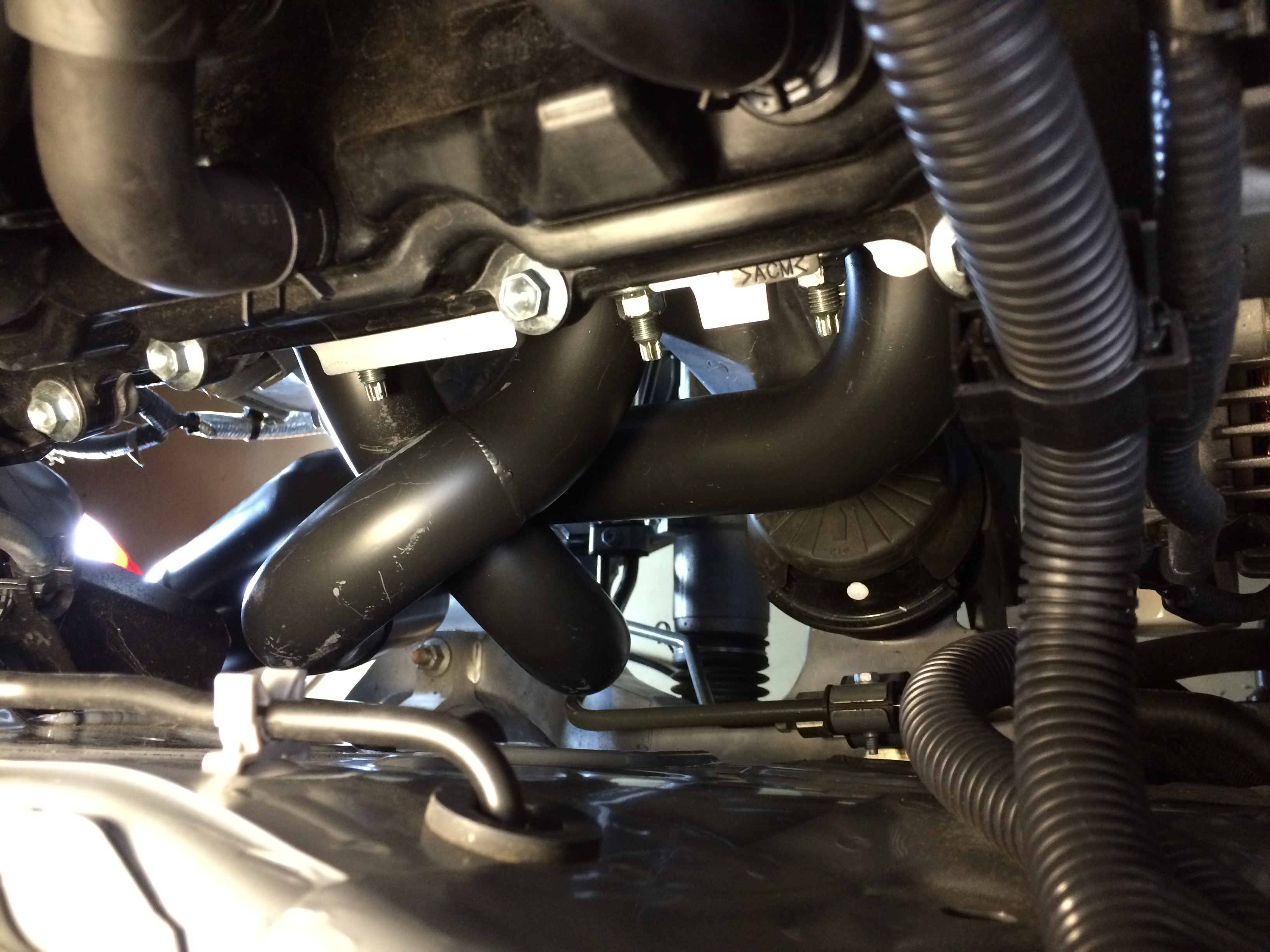
12: View of the driver’s side header. Also in view are a big coolant tube (shiny metal), clump of electrical (black plastic), and A/C lines (black and silver at bottom). For this project you spend a lot of time trying to squeeze in between those things – it pays to have small forearms here. In addition to the squeeze there are some sharp parts which will slice you up.
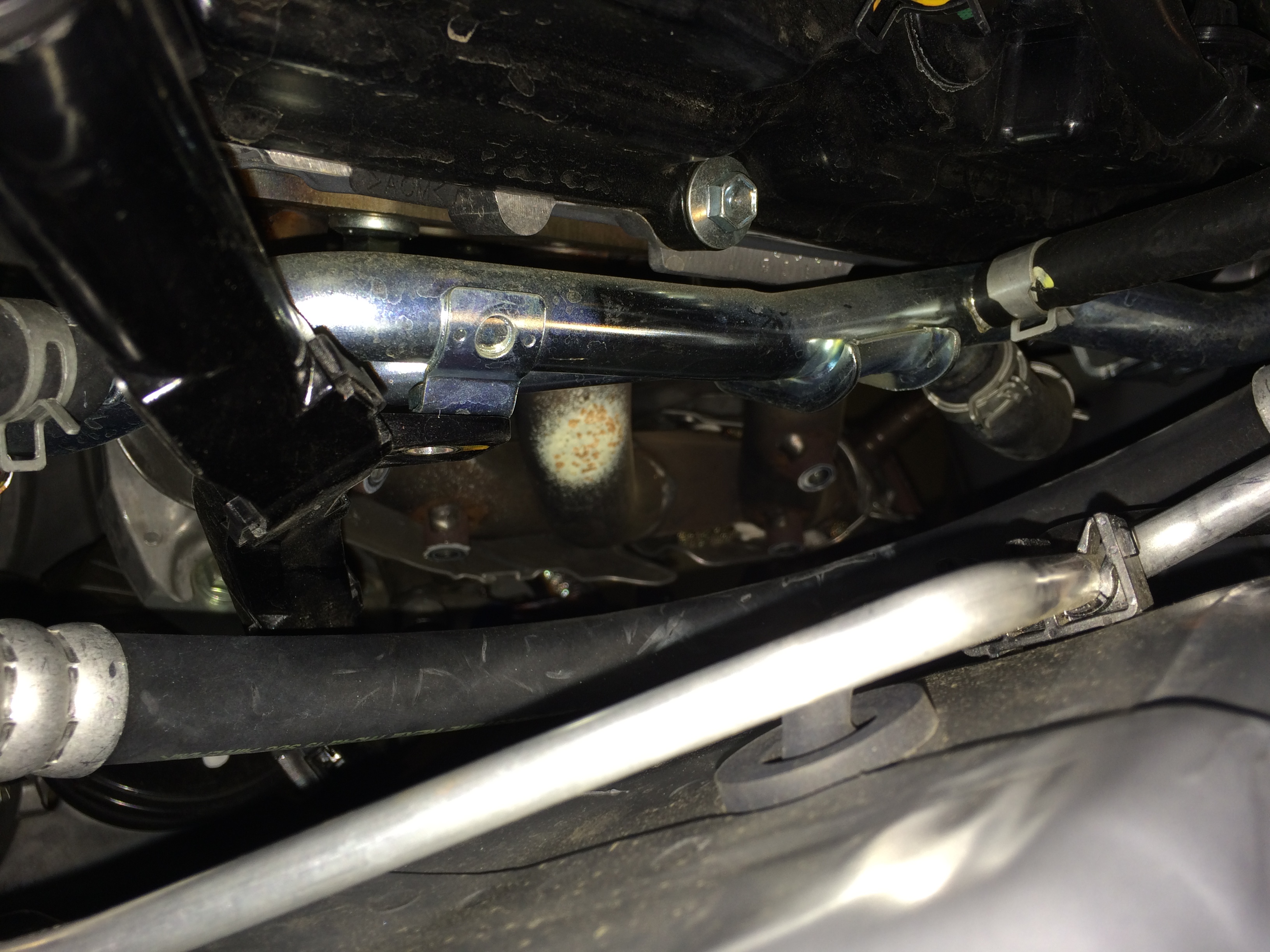
13: To remove all 12 nuts (14mm), I used a deep 6-point 1/2″ drive socket on a swivel-head ratcheting breaker bar thing. Been working on cars a long time and only bought it recently for some other project, glad I had it here.
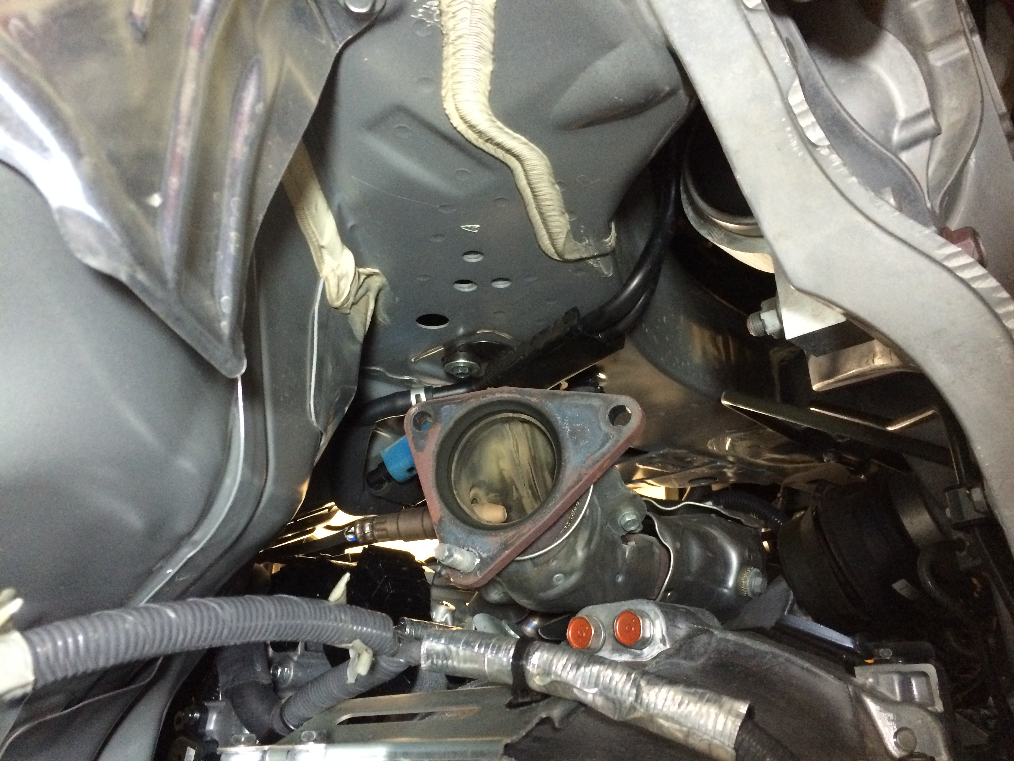
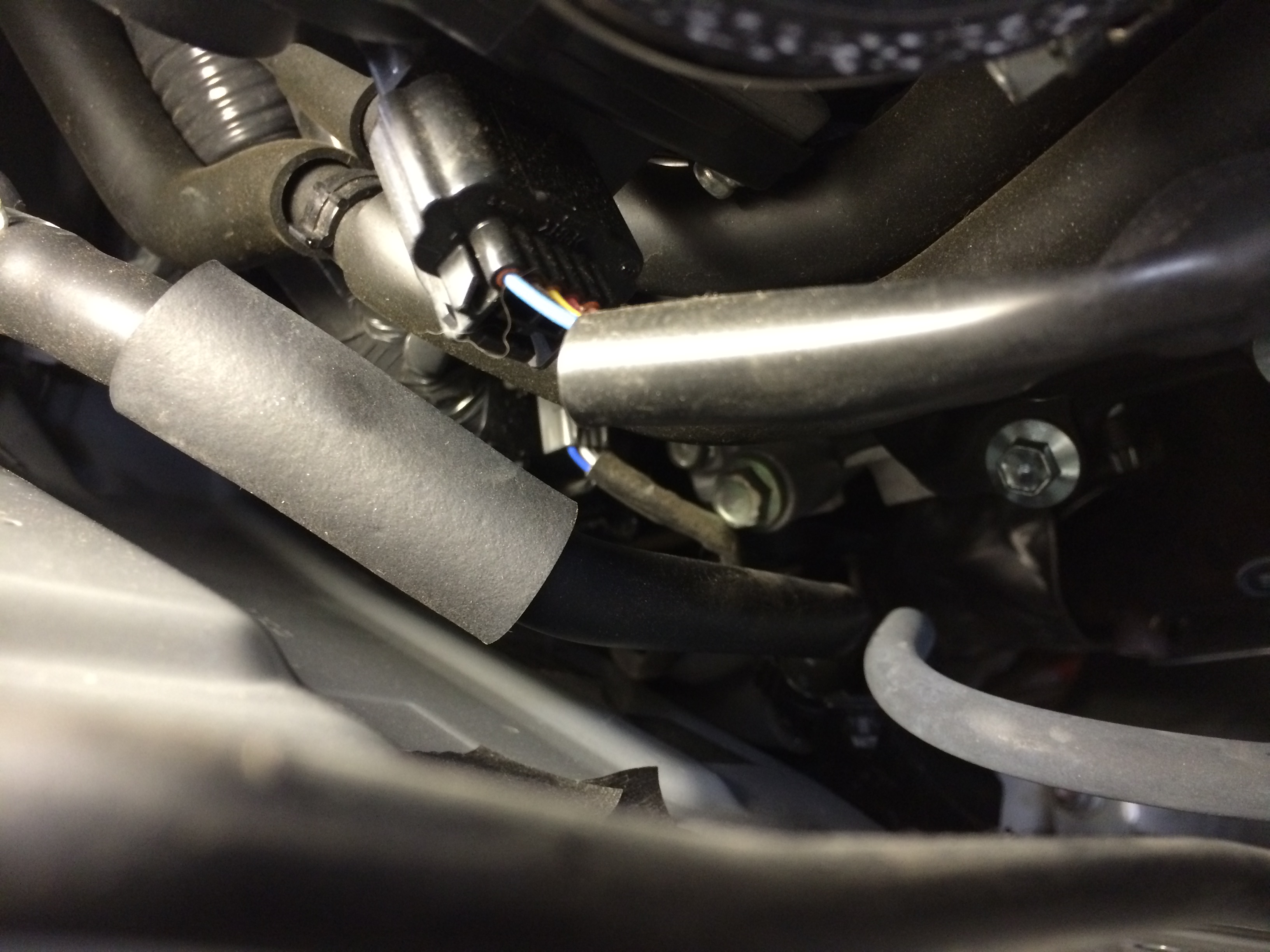
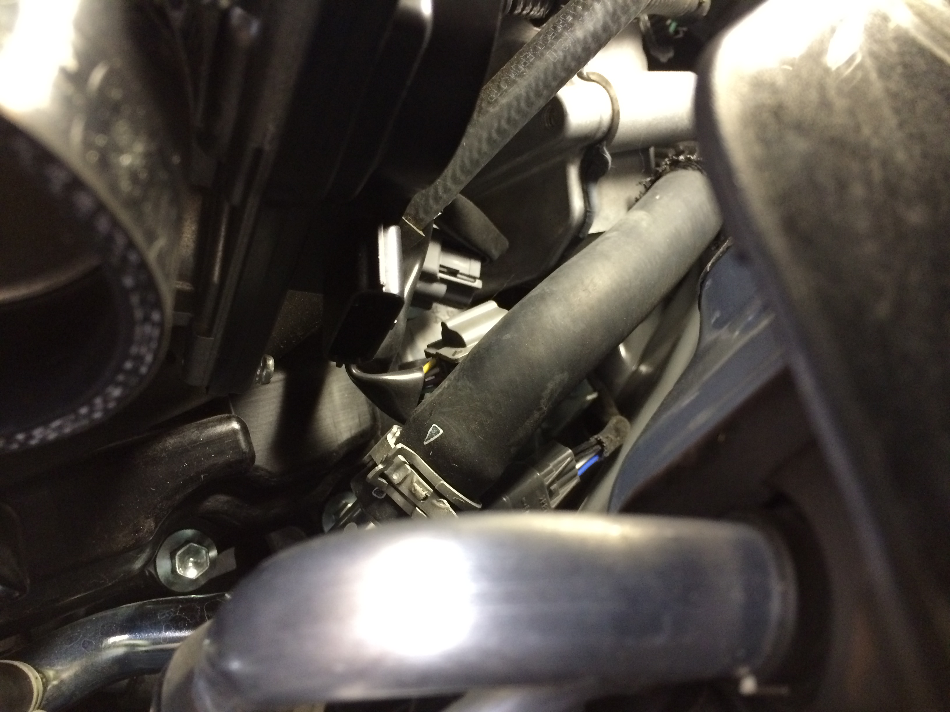
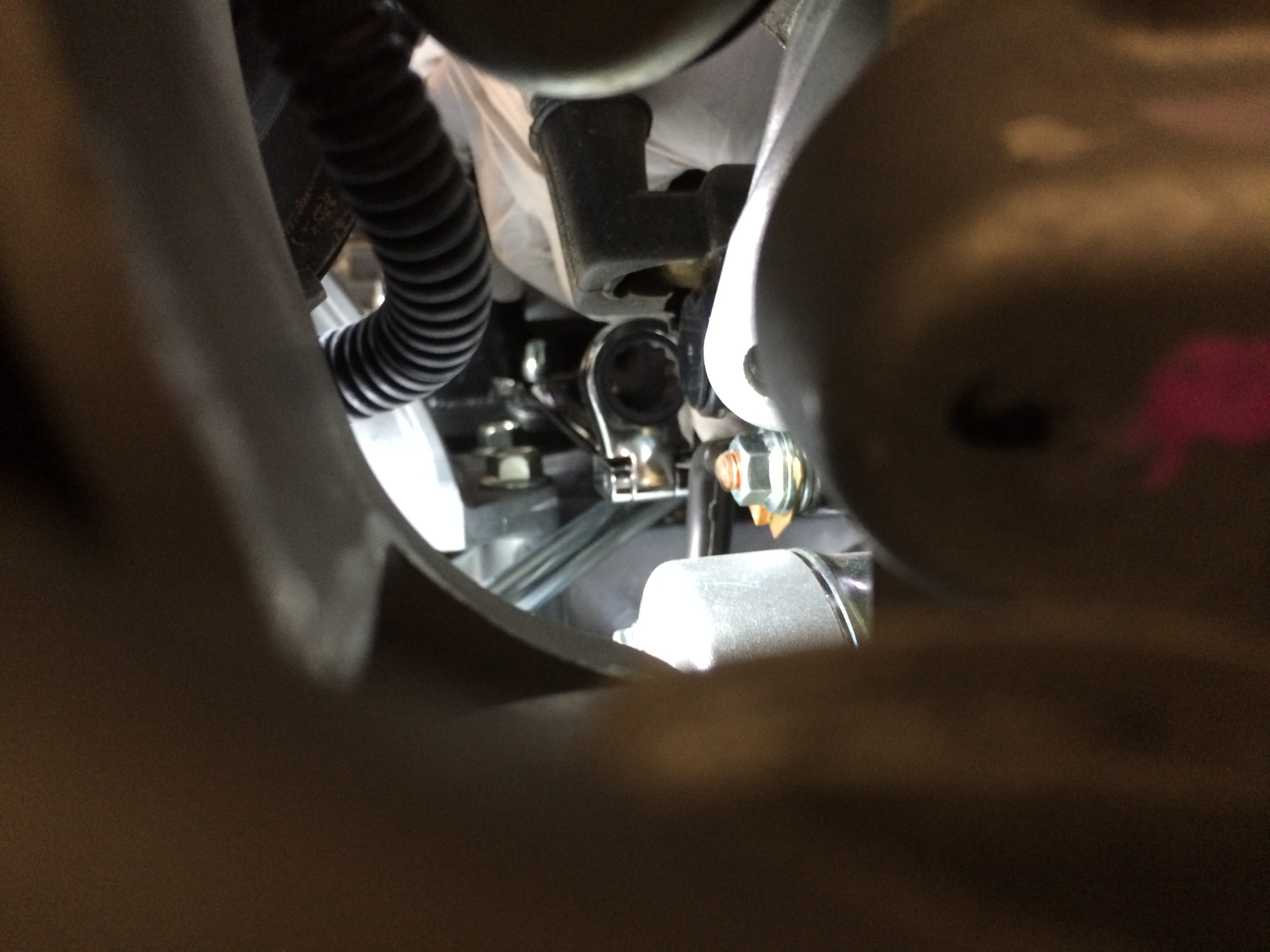
14: Before you can pull the headers you need to disconnect the o2 sensors. I thought it’d be easier to unbolt the sensors after the manifolds were removed to I unplugged the sensors up top and undid them from their little guide brackets on the back of the block. The passenger side, it’s buried back in there.
15: Passenger side stock manifold out! yay!
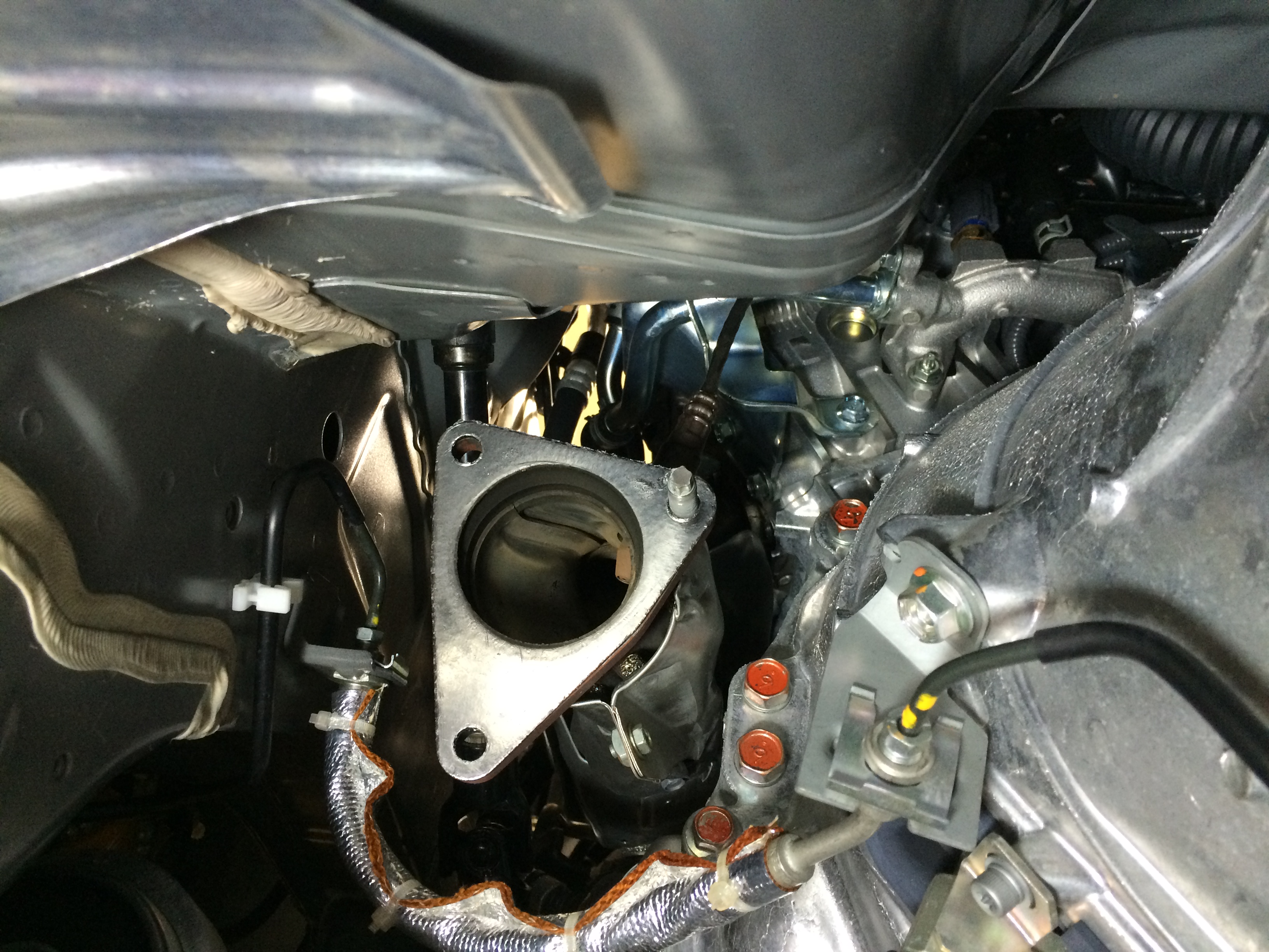
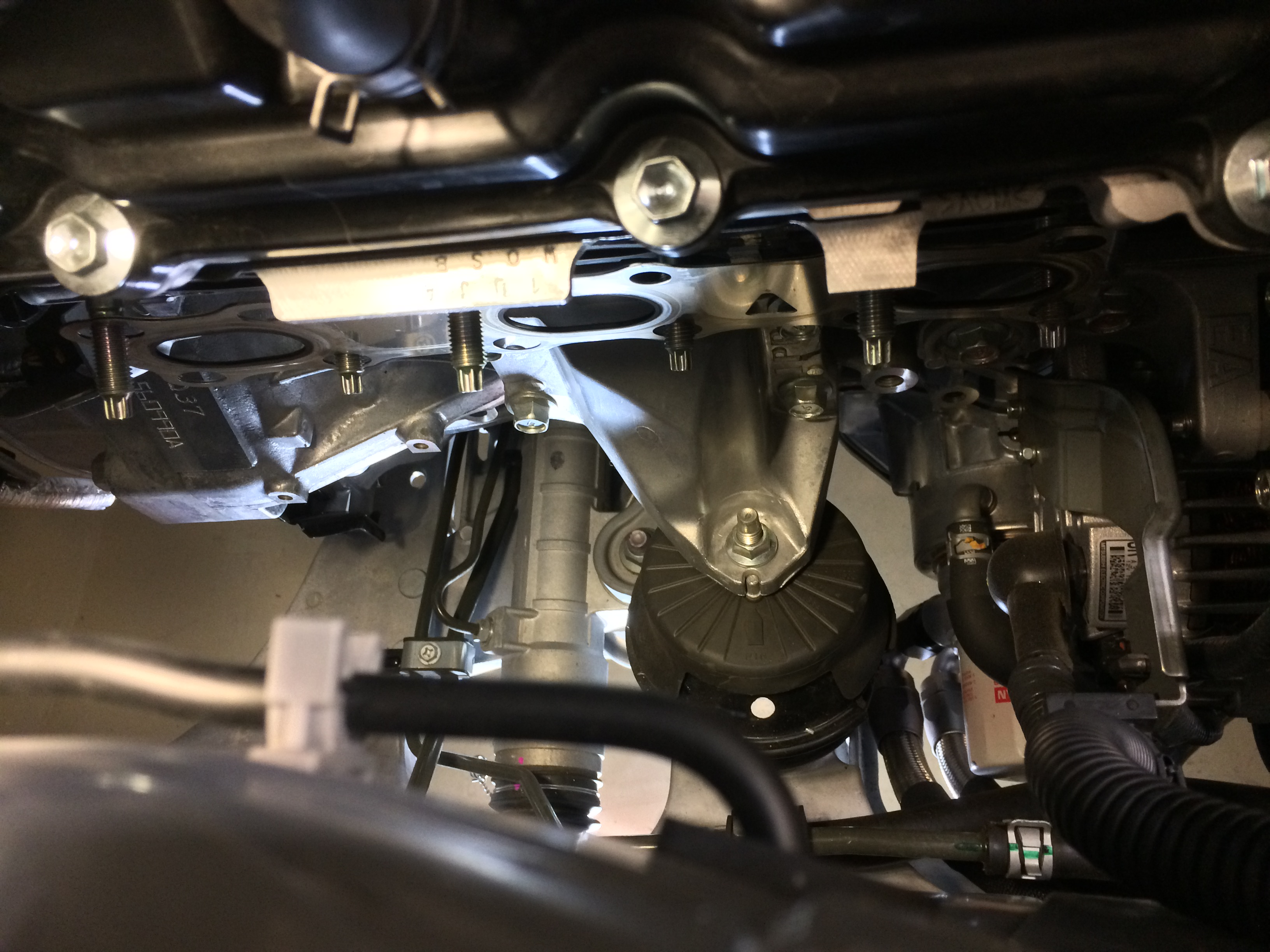
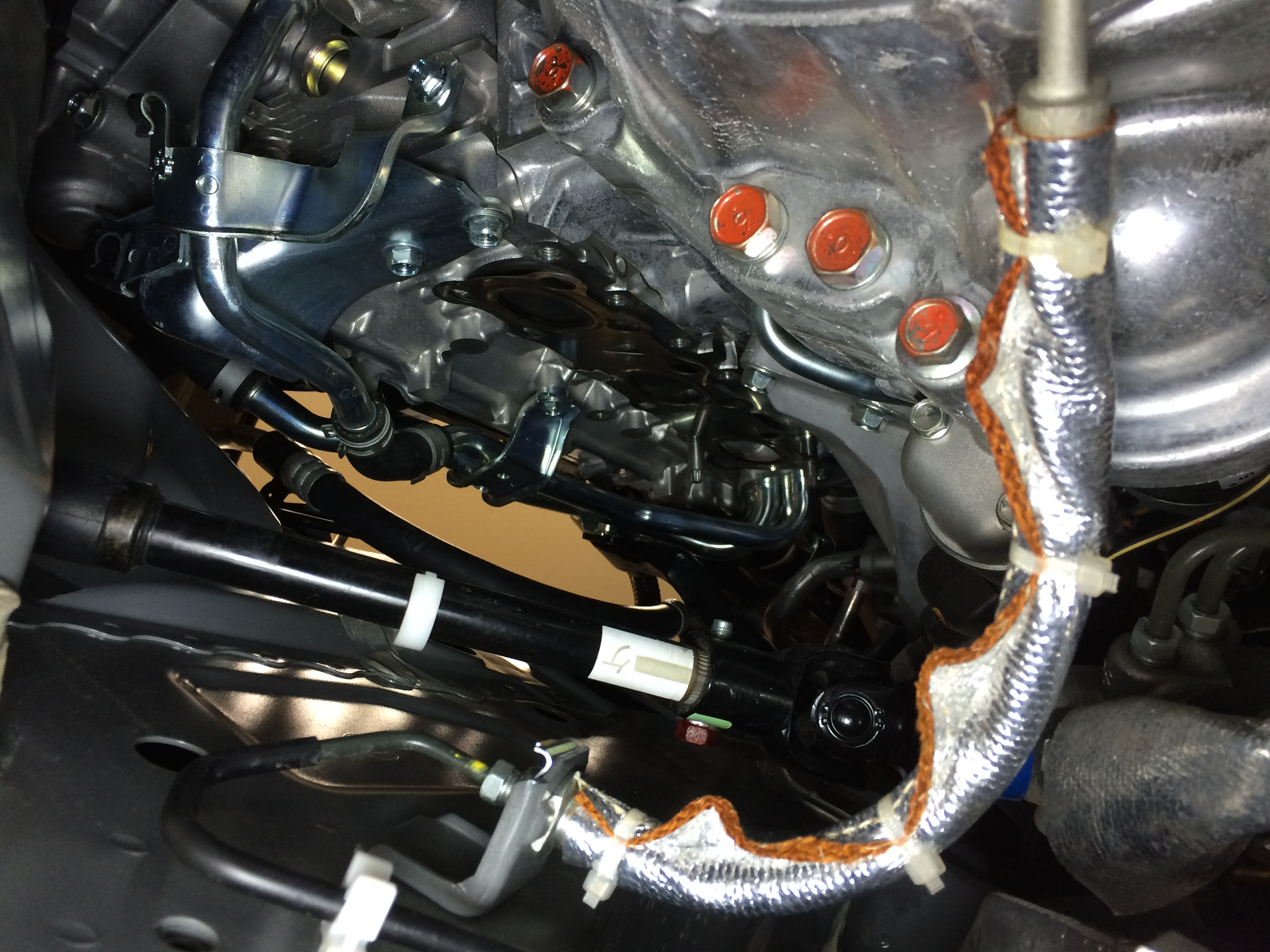
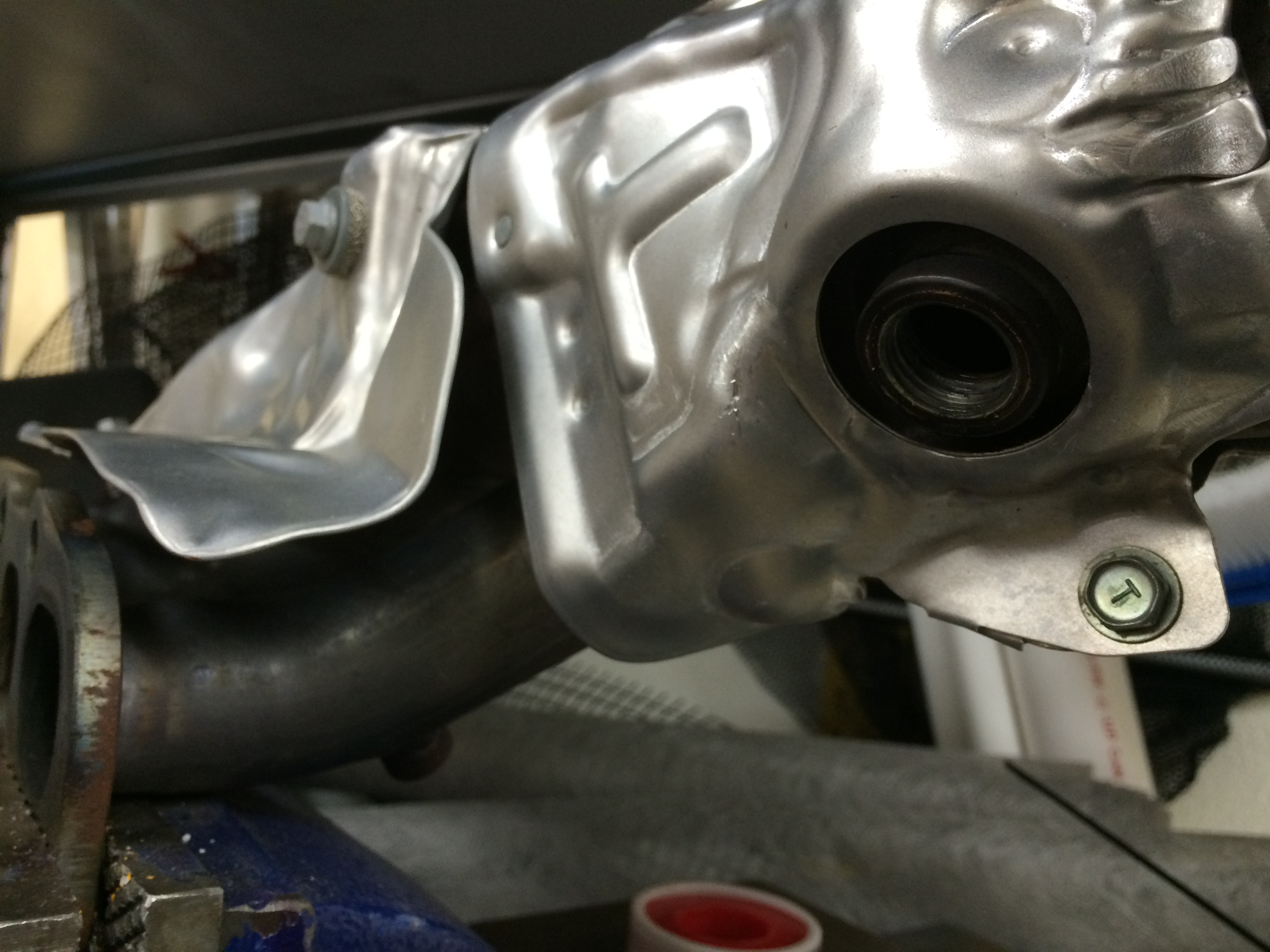
16: View of the passenger cylinder head with the manifold removed. Unlike the black hole of the driver side, light can travel into this space to illuminate its shape 🙂
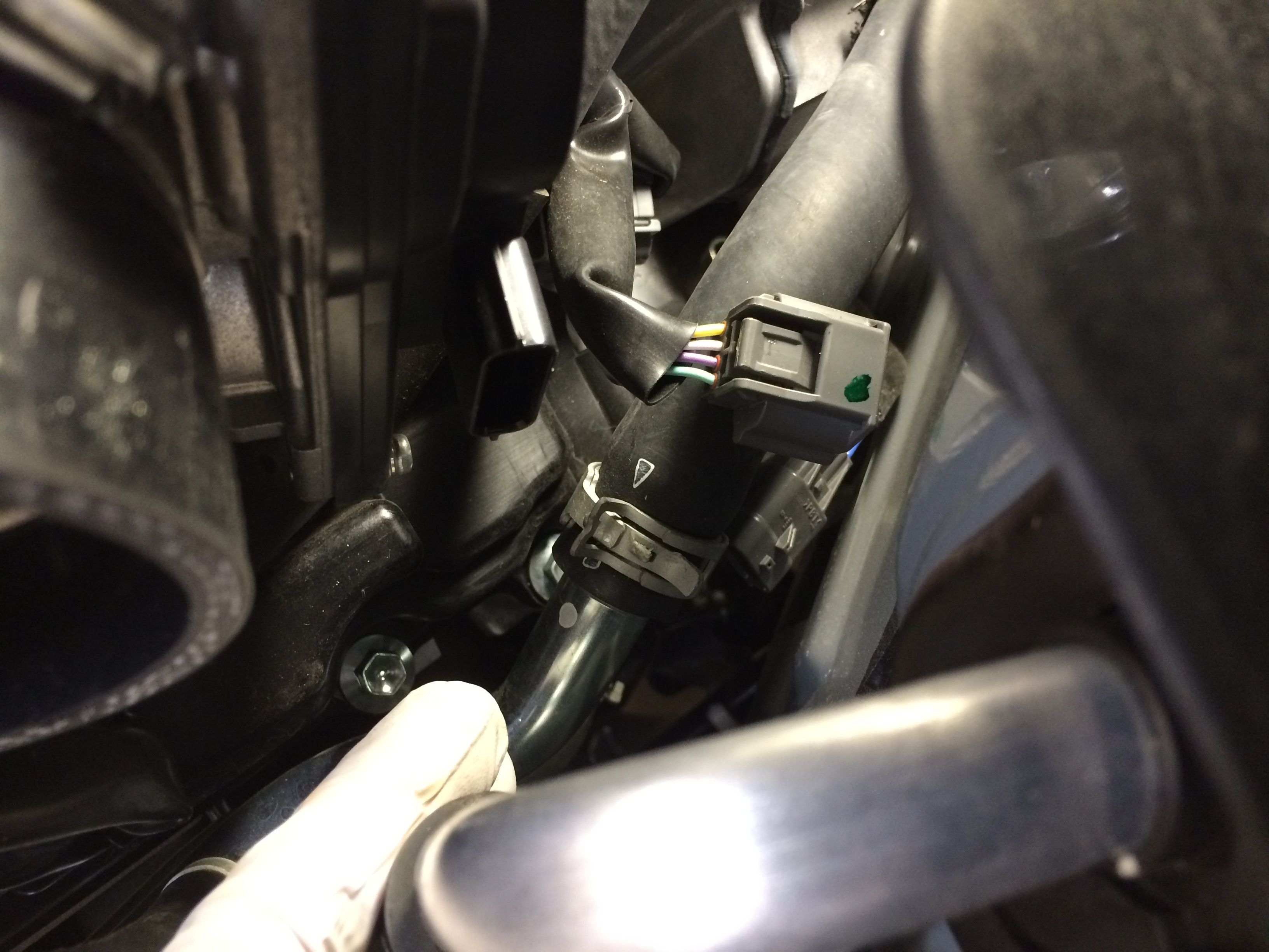
17: The driver’s side o2 sensor plug is harder to get to (a consistent theme). It helped to unplug the connector going to the throttle body.
18: Driver side o2 sensor slid off its little post and unplugged
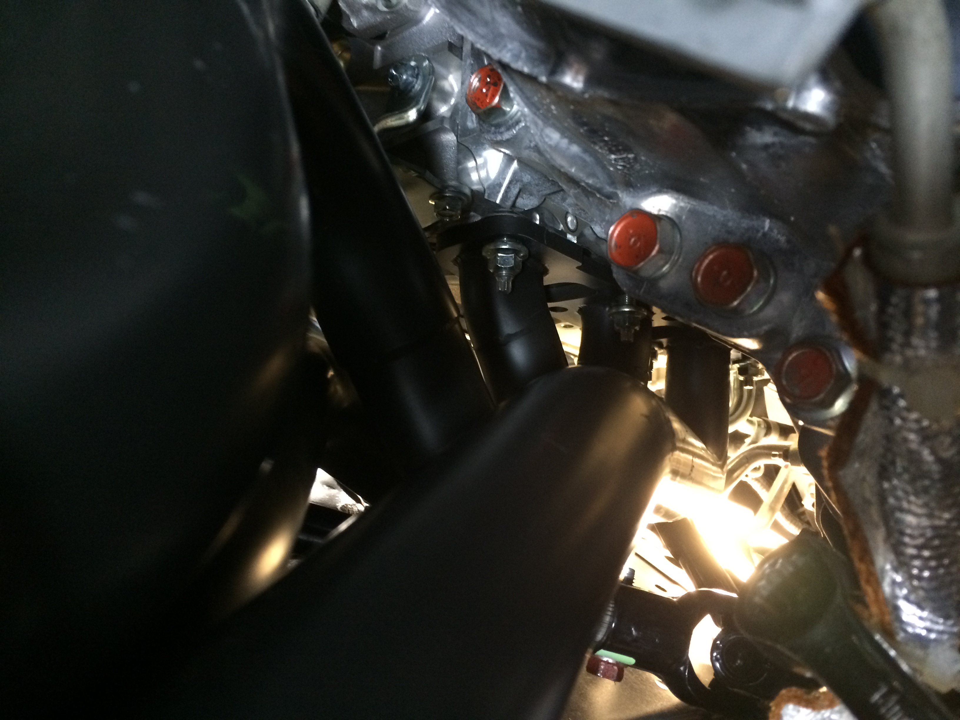
19: Driver side – out! Got it out without having to remove the studs, or mess with the steering.

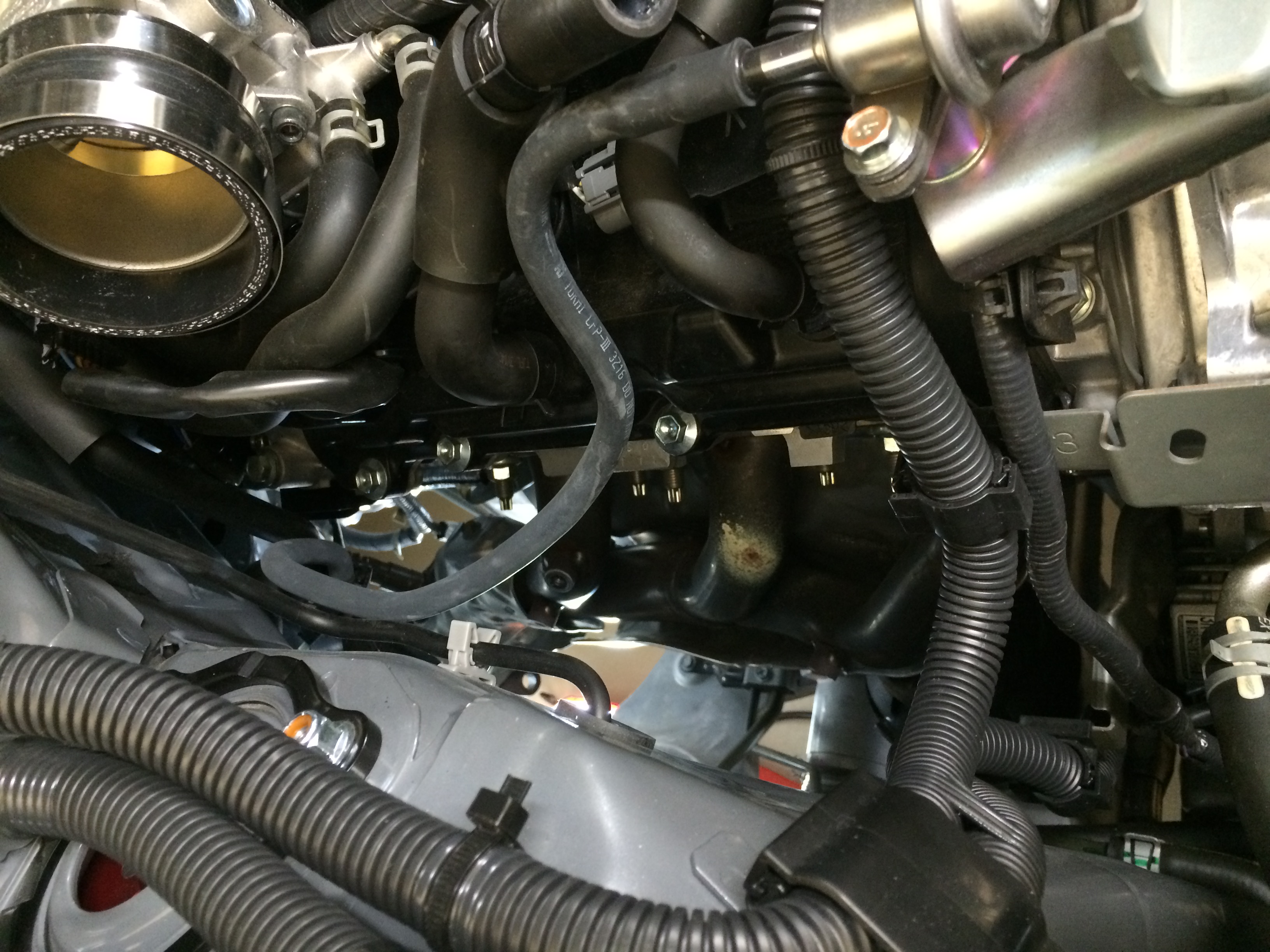
20: Is there a manifold in there still? Eh, can’t tell…
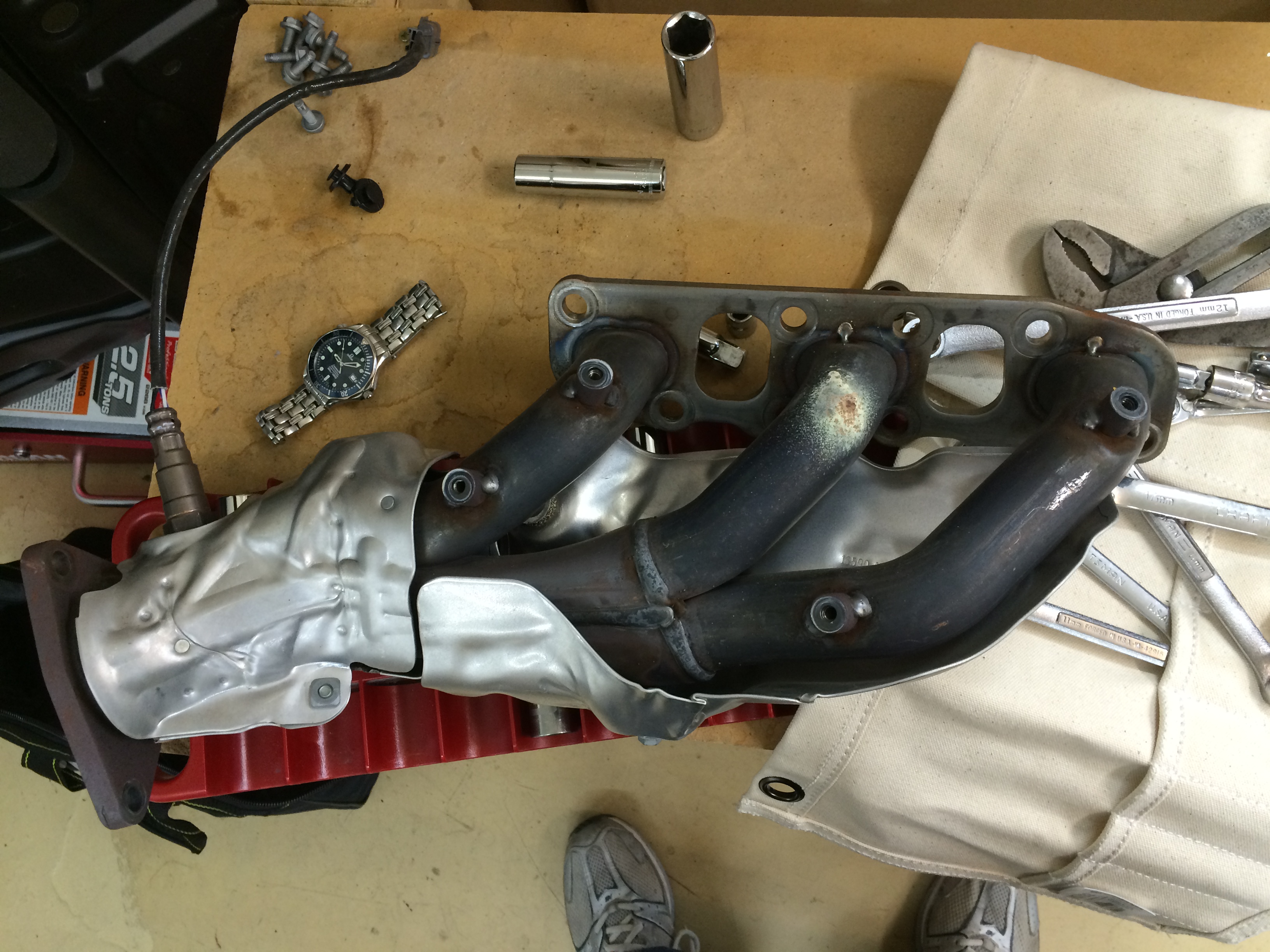
21: The factory manifolds are actually really nice looking for an OE piece. Some guy in Japan (or wherever they are designed) probably shakes his head when he sees people swapping headers.
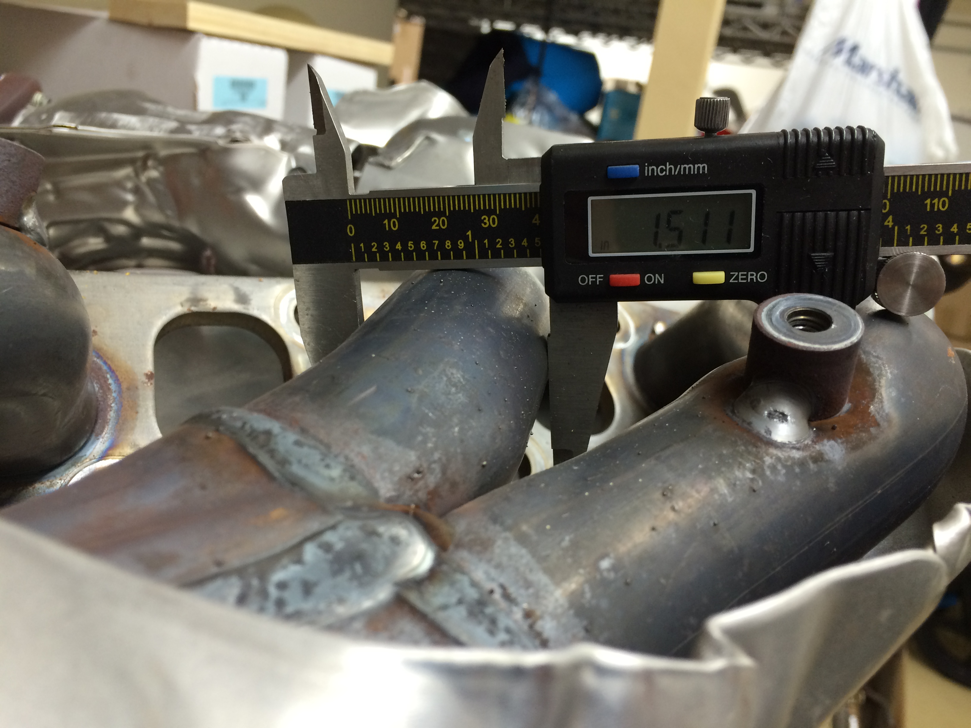
Header primary diameter is a big factor in the shape of an engine’s power curve. Stock pieces are about 1.5″ – which in a super overgeneralized hand-wave, is a little “torquey/small” for an engine making 50-60 whp per cylinder.
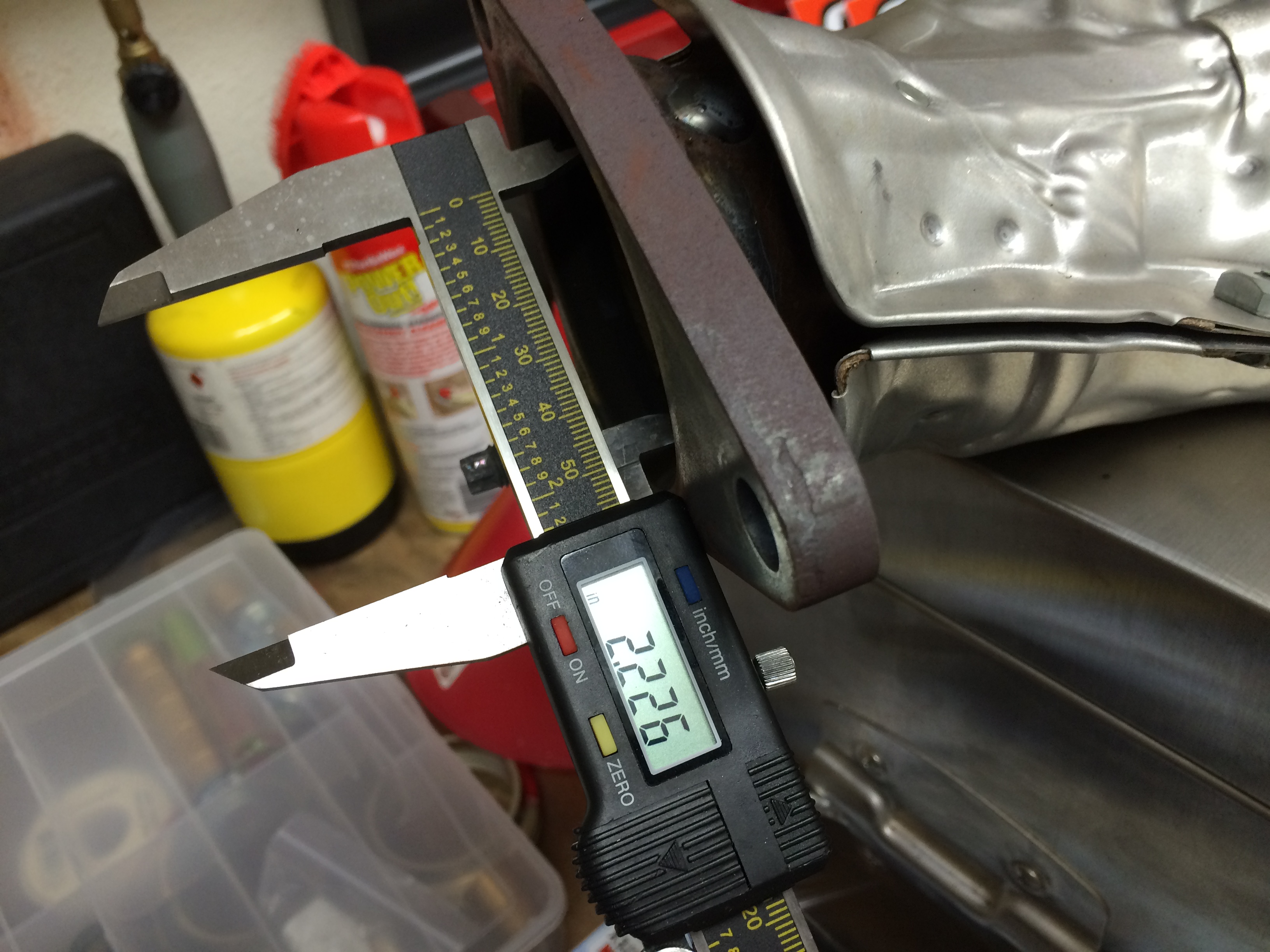
22: Collector size is appropriate for the primaries but a little choked overall.
Evening 2 ends here, another 2 hours.
Evening 3 begin – this was the long one:
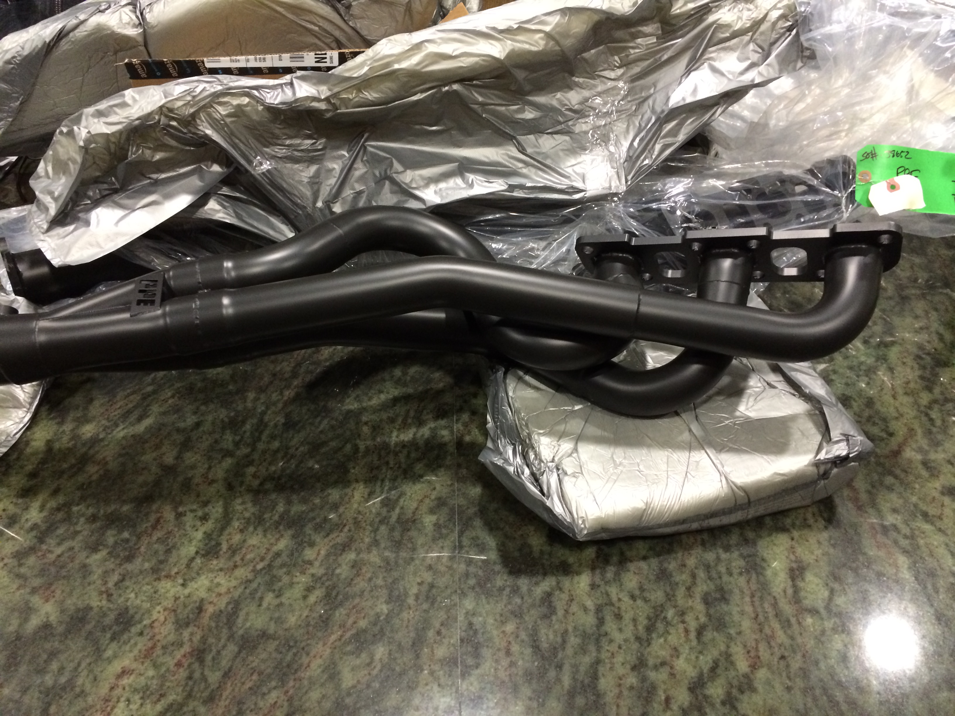
23: Unboxing the PPE’s
24: First to attempt install was the passenger side. I recommend doing that with everything because it’s a massively more accessible mirror image of the driver’s side. What you learn here without a ton of pain, you can apply to the other side.
It wouldn’t go in and something seemed really wrong here. This was one of my first heart attack moments. Check out the flange compared to stock:
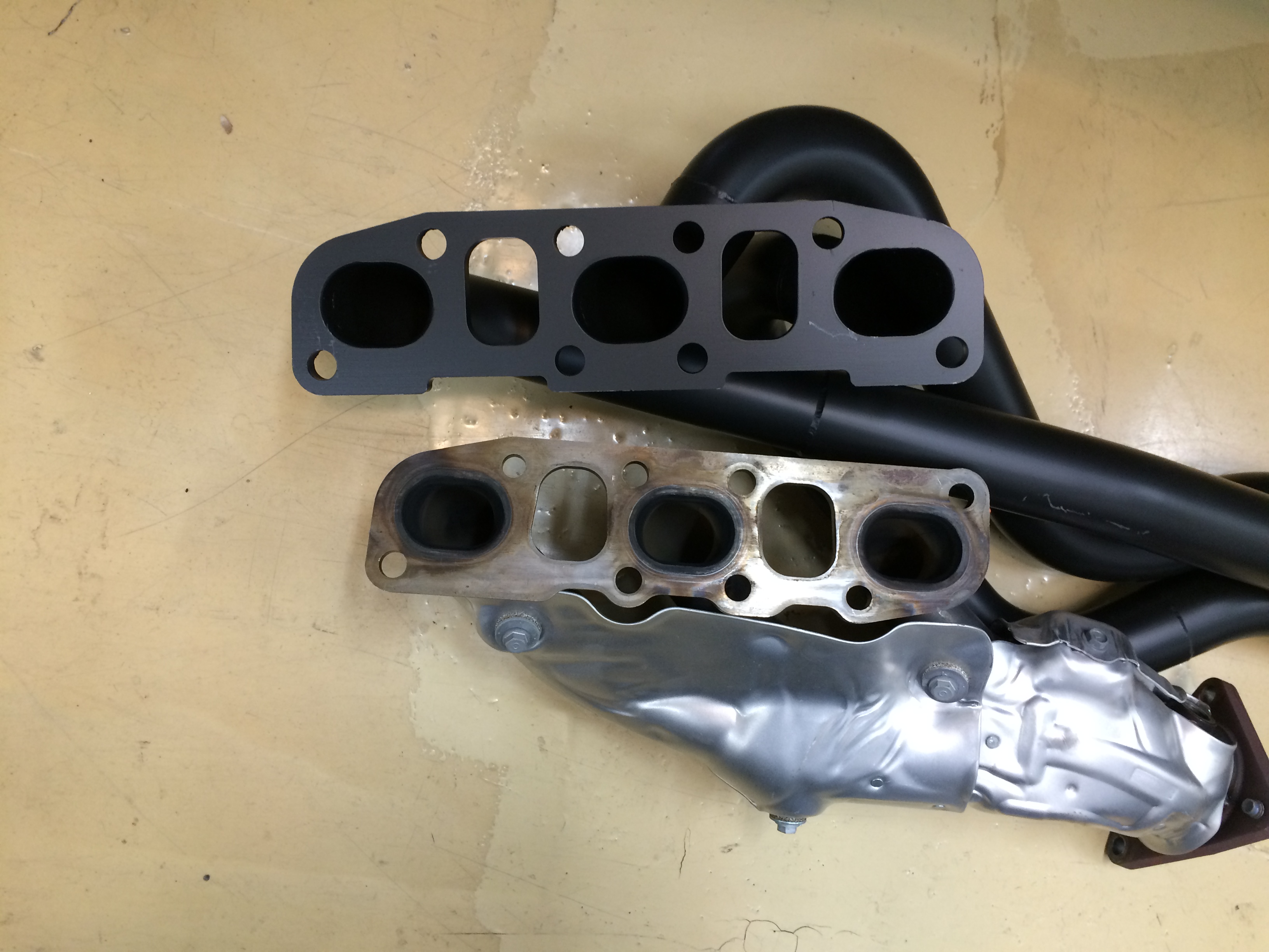
For a while I was surveying the shipping materials to be sure I could send them back. The flange seemed upside down, but then I saw the front (left-most in pic) cylinder was correct. Took me a while to figure out, the gasket had holes in the right places, but also the cylinder head had the holes already tapped in the perfect spots?!?
So I swapped the diagonal positioning of the rear ones – it still wouldn’t go in, but now because of a lack of room.
Left the middle cylinder’s studs in (original holes) and got the header on, and re-installed the other studs. A ways into securing things I realized the middle would have to be swapped too..
Eventually got it in, studs in (they have a 6-point star end that needs a 1/4″ wrench or socket – 6mm too small, 7mm too big) and nuts tightened.
25: Passenger side header in. Three top nuts and forward lower tightened from above. Middle and rear lower tightened from below with wrenches.
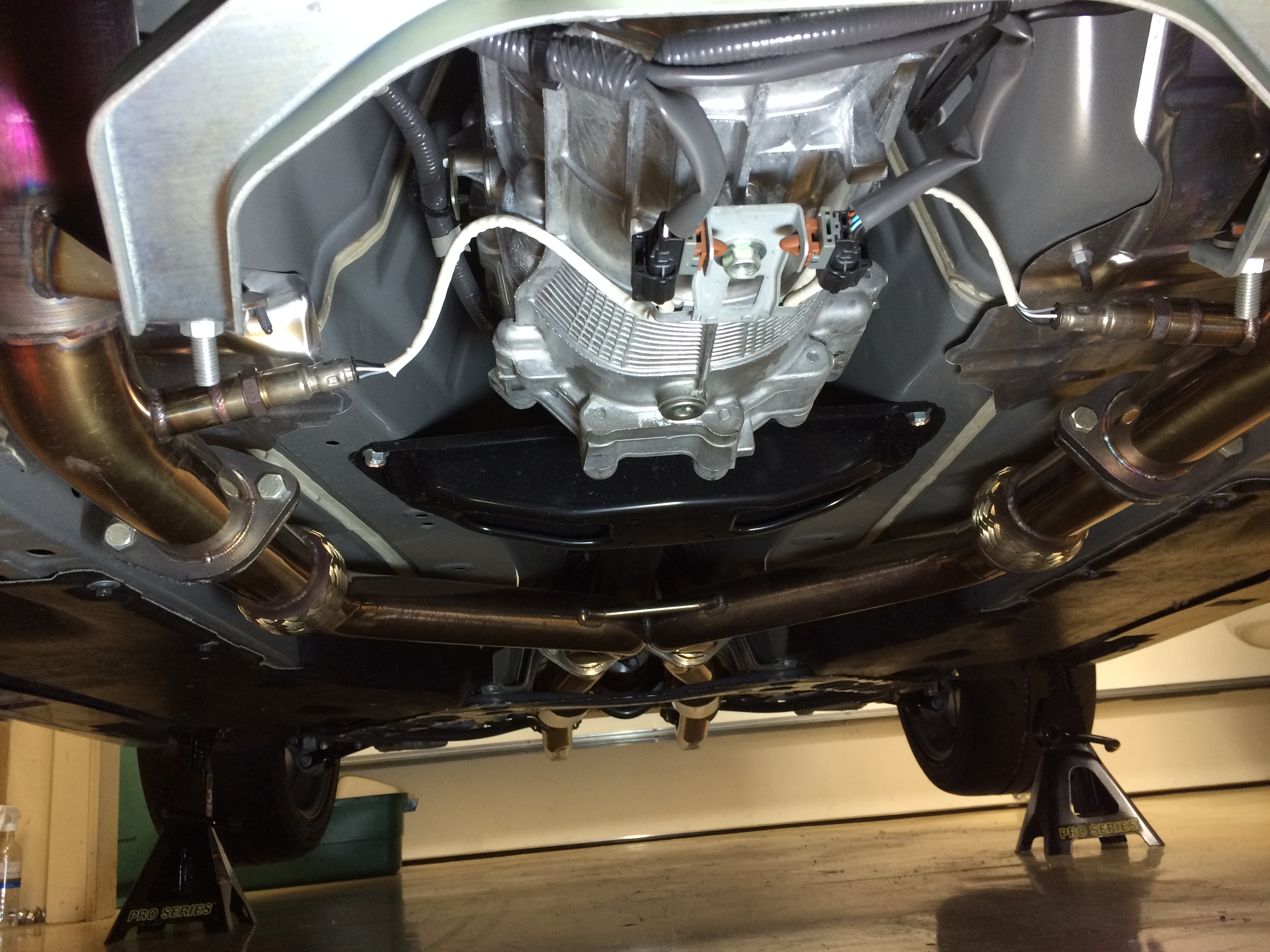
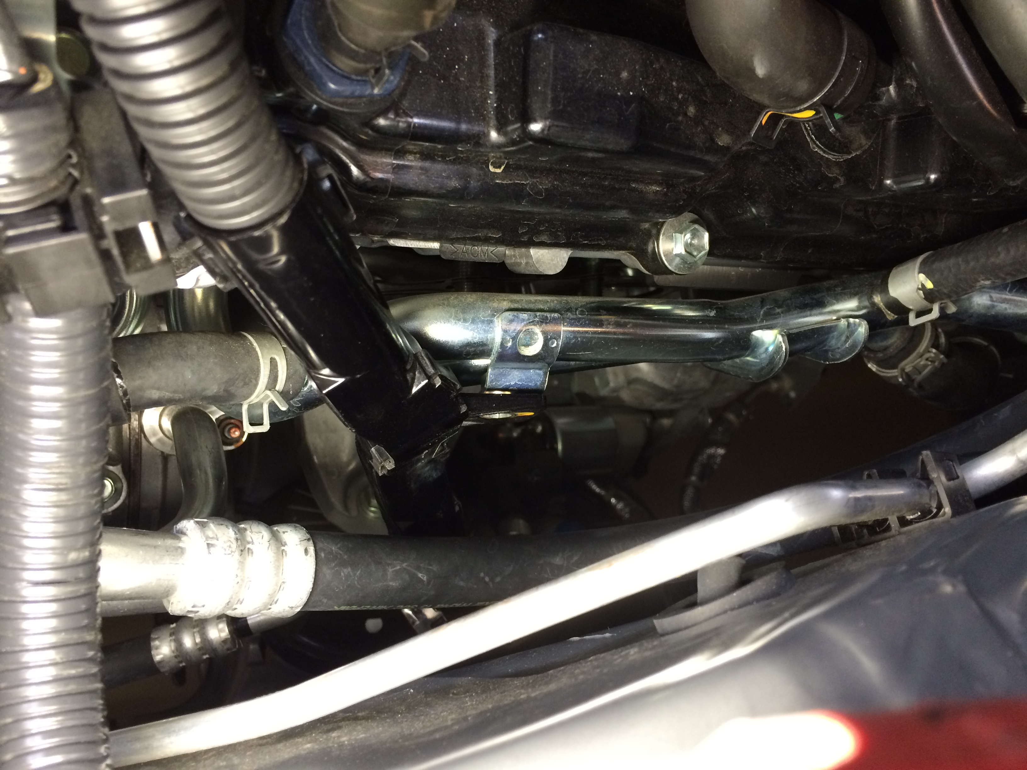
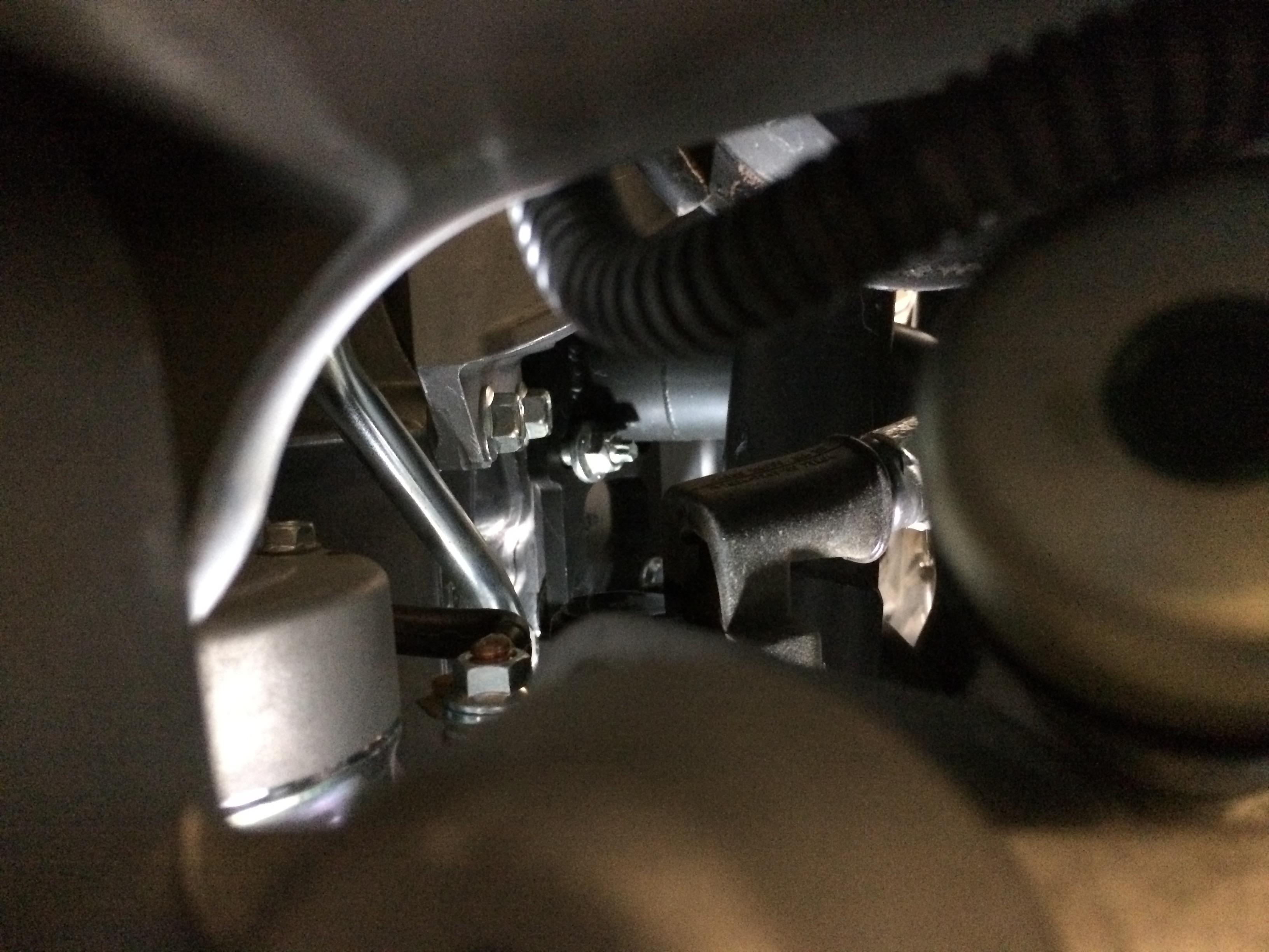
26: Starting point for driver’s side install. Lots in the way. Had to raise the front of the car a bunch more to allow it to be angled past the clutch parts. The steering shaft MUST be disconnected and slid way up inside the column. To do that, remove the red-headed 12mm bolt, and remove the white plastic clip thing on the shaft. The splined end of the column is keyed to the receiving end on the rack. The problem is once you slide the shaft up past where the white plastic piece is, it becomes unkeyed internally up in the steering mechanism. Take care to not alter the relative clocking of these components!
27: The lessons from the passenger side helped but getting this far is awful. To get the very tip of your fingertips holding the exhaust studs to the place they need to be, requires sacrificing your forearm in the jaws of the surrounding tubes and things. It’s extra painful because as you are moving your fingers, it makes the forearm area hurt more, as your finger’s tendors try to move while clamped in a vice.
28: The three top nuts aren’t too bad, same for lower front. The rearmost lower is accessible with a wrench from underneath (again way harder than passenger side) but the middle lower nut…well, all I could picture in my head is IMPOSSIBRU
That is the single toughest fastener to deal with in this whole project.
This is a view from directly underneath, an unobstructed column way too narrow to allow for any tool angularity. Making it worse, I was too lazy/dumb to bring the front of the car lower again after raising in step 26. That meant doing anything from underneath meant holding an abdominal crunch to get the arms/shoulders high enough to reach stuff. I’m a typically beer bellied american so I called it a night at this point so I could look at it fresh the next day – was past 2am, a 5 hour work session.
Evening 3 (Friday night) done, evening 4 begin.
29: Contemplating the problem, I thought I’d get some swivel-head wrenches, on the hopes I could find some plane that would allow me to tighten it. Because of the V shape of the motor, tools want to fall off if not held in place. But there’s not much in the way of access to hold in place, not to mention allow for any installation motion.
The other problem was the nut was close enough to the primary tube, not enough room to fit the closed end of a ratcheting wrench (at least my mediocre-quality gearwrench stuff) on it.
What I ended up stumbling into, was to use the open end of the swivel-head wrench like so:
This shortened the effective length of the wrench enough that I could move it 1 “flat” (1/6th of a turn) at a time within the space available. At the same time, the flex head being in that perpendicular plane allowed me to both hold it onto the fastener, but also torque it, with one hand.
After a few complete revolutions I had to keep stopping every 4-5 flats to let the blood flow back into my arm. Access was from above the lower control arm and up through the maze of tubes. But at last, the hard mechanical part was done.
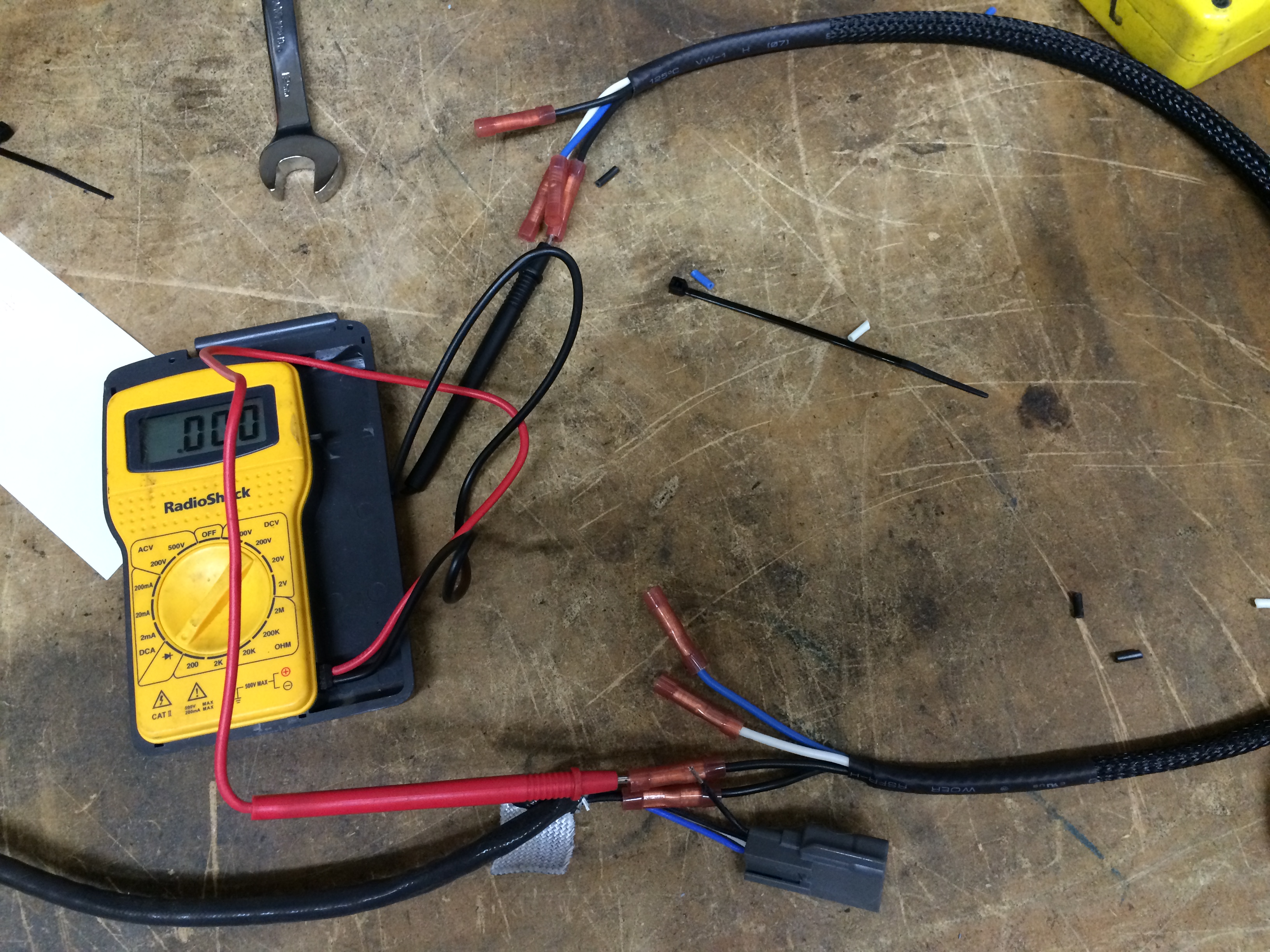
30: An unprepped o2 sensor extension
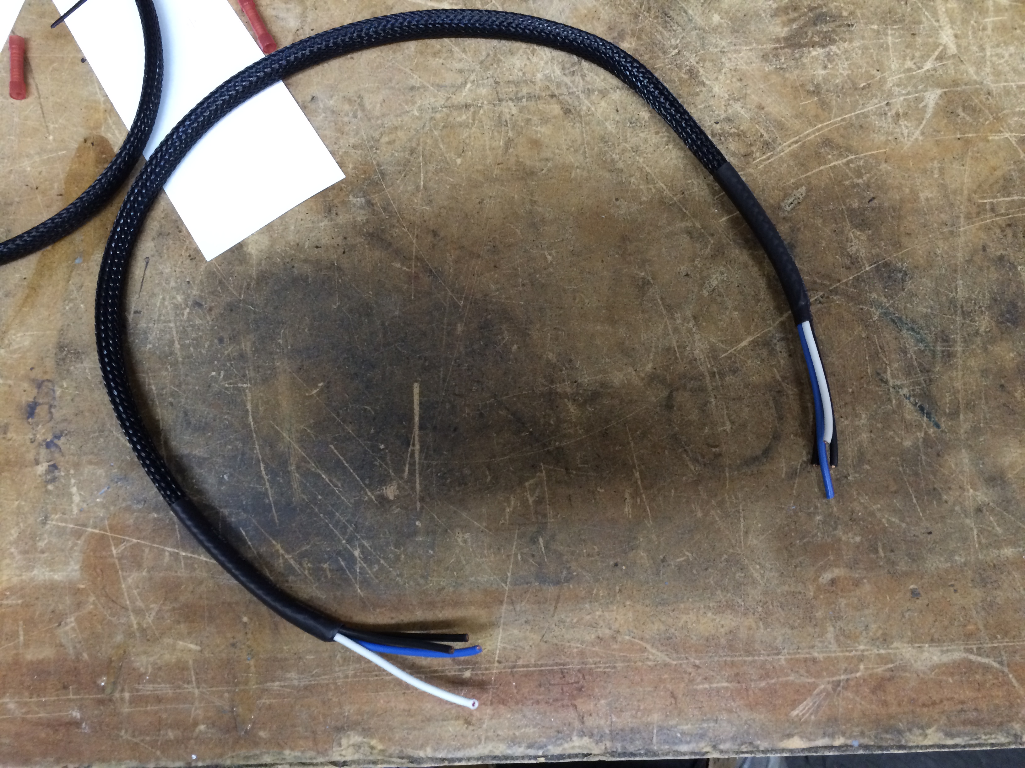
31: Ends stripped and crimped
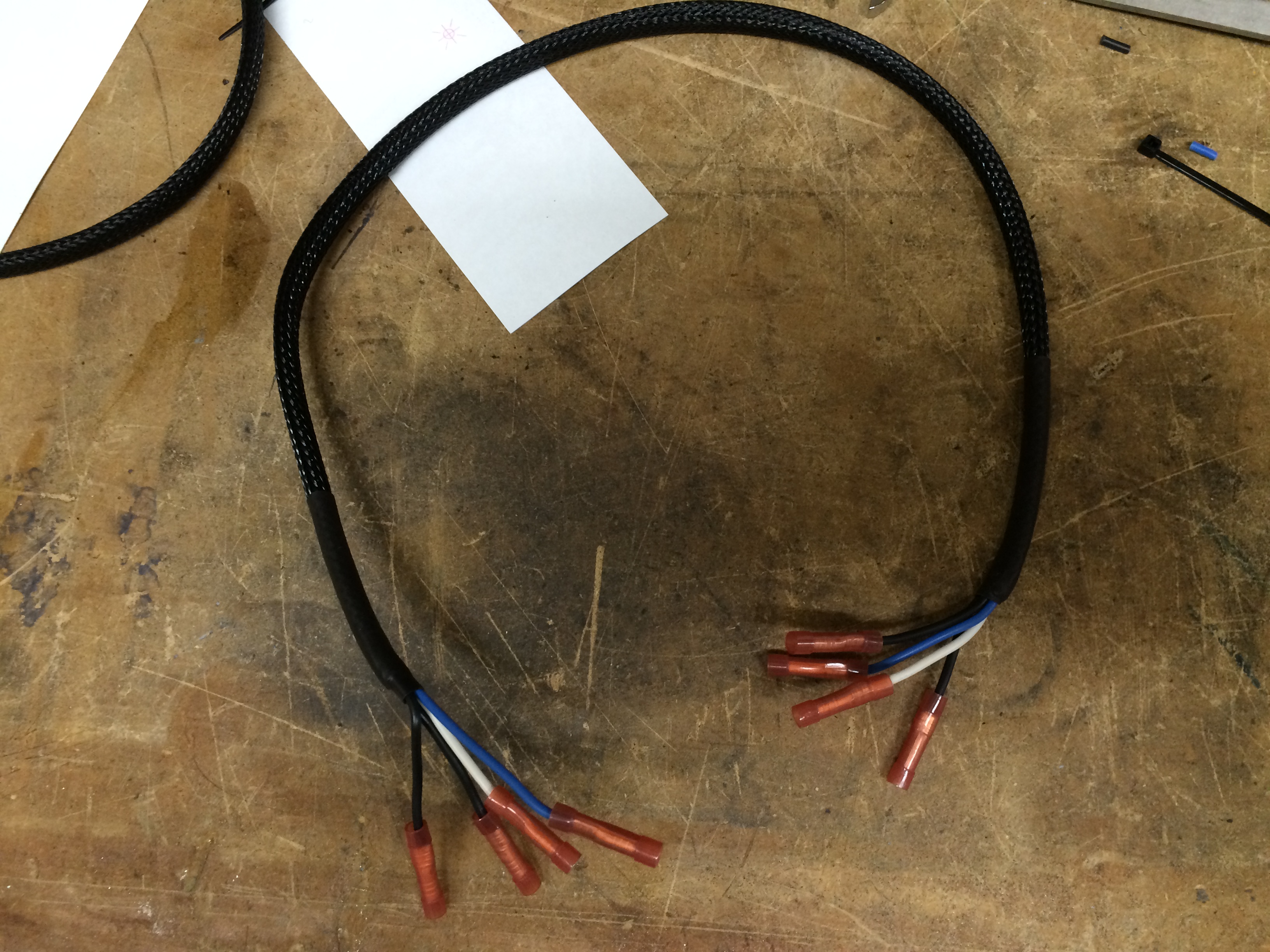
32: I extended up near the factory plug to keep the nice factory head shielding in place down at the header end.
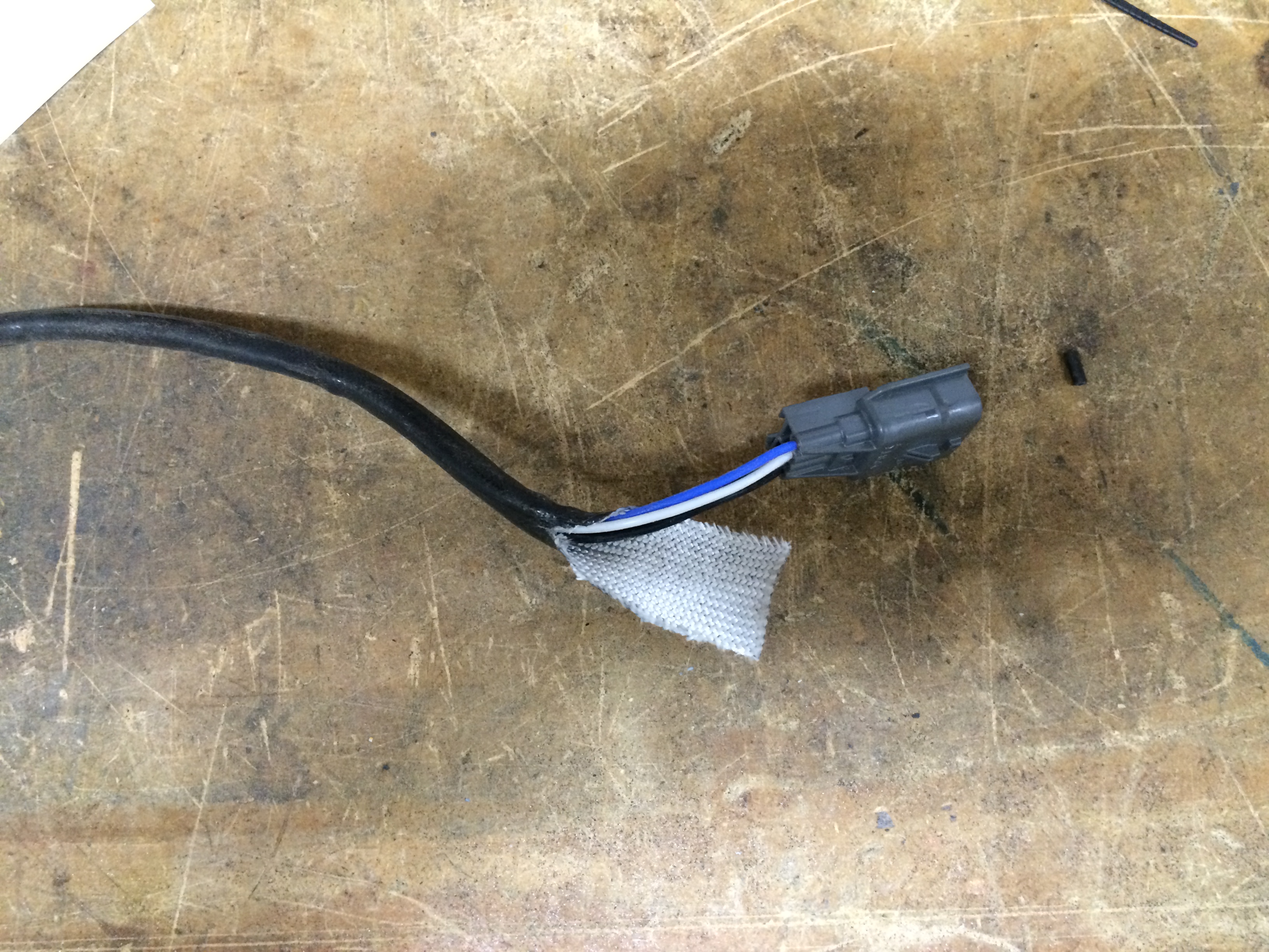
33: Some people have had trouble with this. There are 2 black wires, 1 blue, 1 white. I recommend cutting 1 black wire, crimping on one side, then checking continuity to ensure you’re attaching the correct end on the other side. Once that’s done, you can cut the other 3 (since there’s now 1 of each color).
34: One of my forward o2 sensors boogered its threads upon removal from the factory manifold, even though I treated it nicely on the bench. It wouldn’t thread into the PPE header, and it was midnight on a Saturday night – exhaust shop and dyno appt Monday, leaving for big race Wednesday, no time to wait for a new one, and I don’t have a tap/die tool in that size. What to do?
What I did was use the other factory manifold where the sensor had come out cleanly. Lubed it up a little and with some finesse, was able to use it to repair the o2 sensor’s threads enough to get it to tighten and seal nicely in the new header. Heart attack #2 averted!
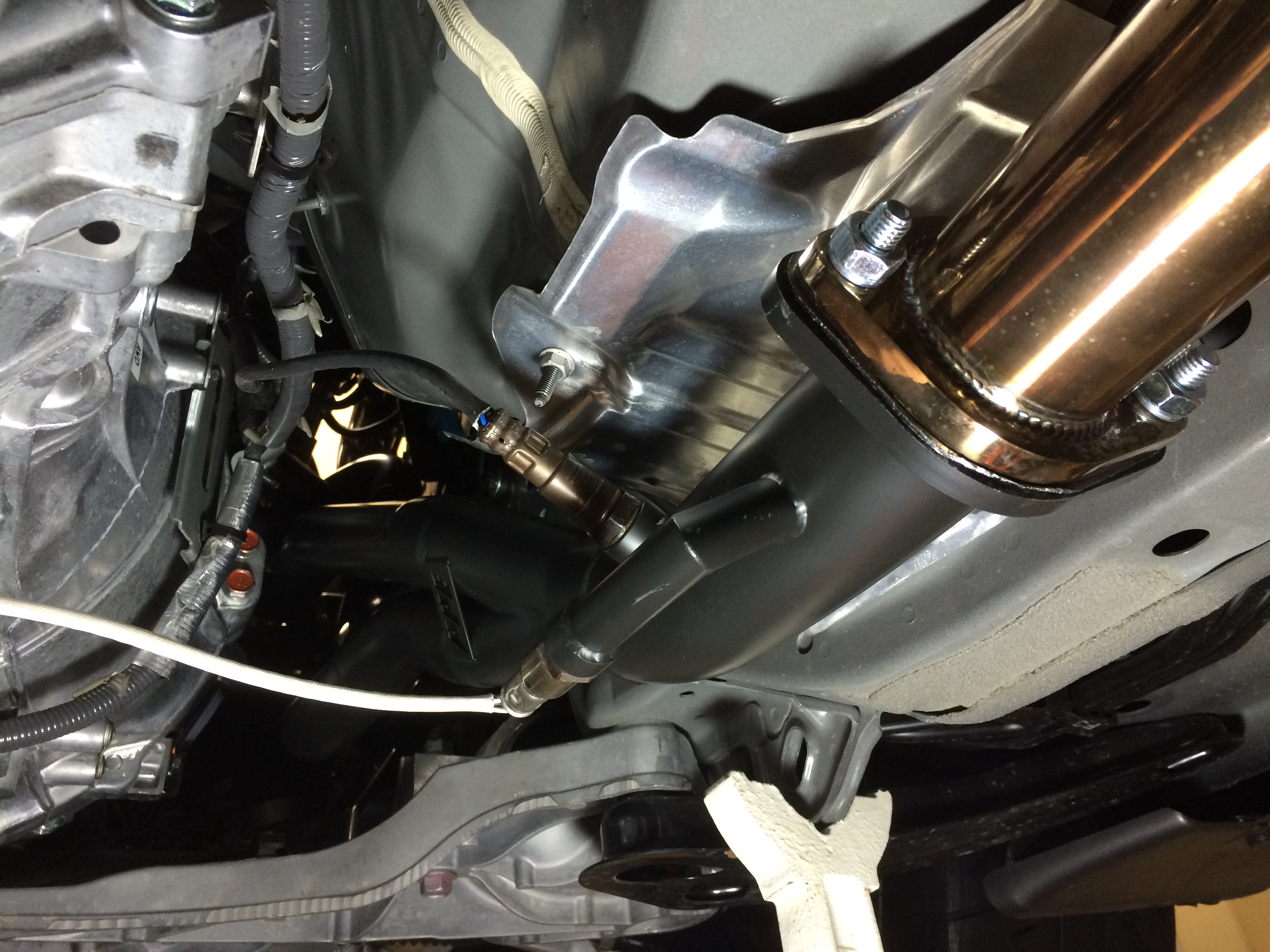
35: Passenger side installed and wired up.
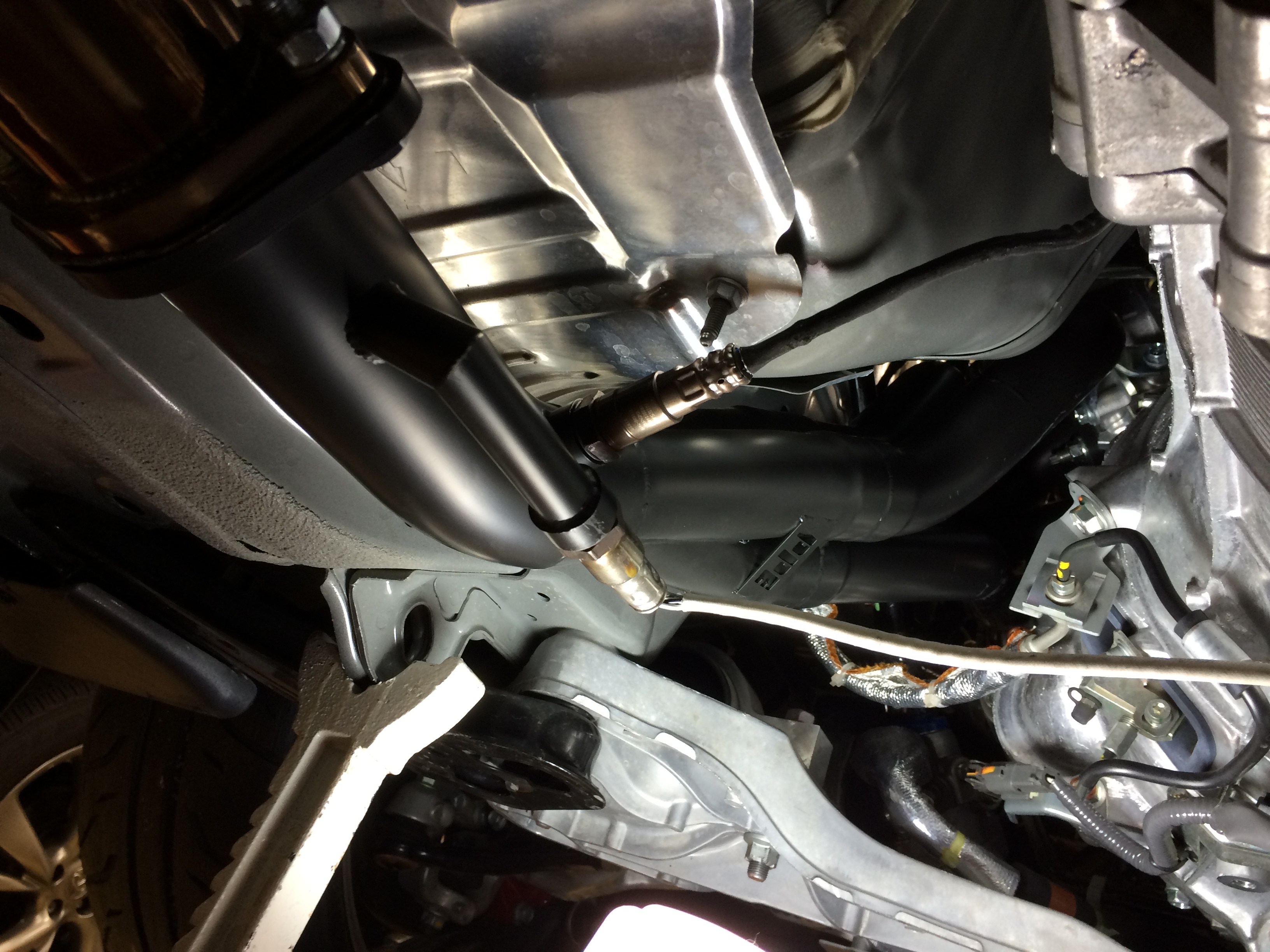
36: Driver’s side installed and wired up. The o2 sensor wires on both sides need some help getting secured in a way that keeps them from getting melted. This wasn’t too hard but at this point I discovered the transmission (which is right there and you’ll contact at this step) has some weird casting bumps that are extremely painful to touch, much less rub against. It feels like 20 grit sandpaper that also delivers an electric shock!
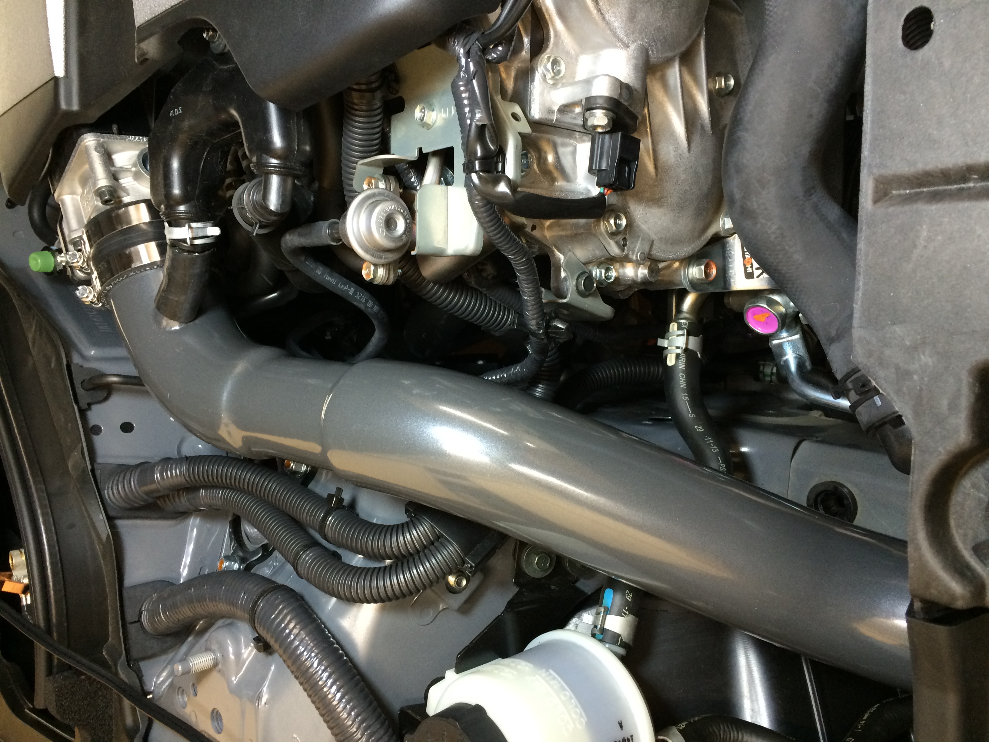
37: From above, you can barely see the header in place once the intake is reinstalled.
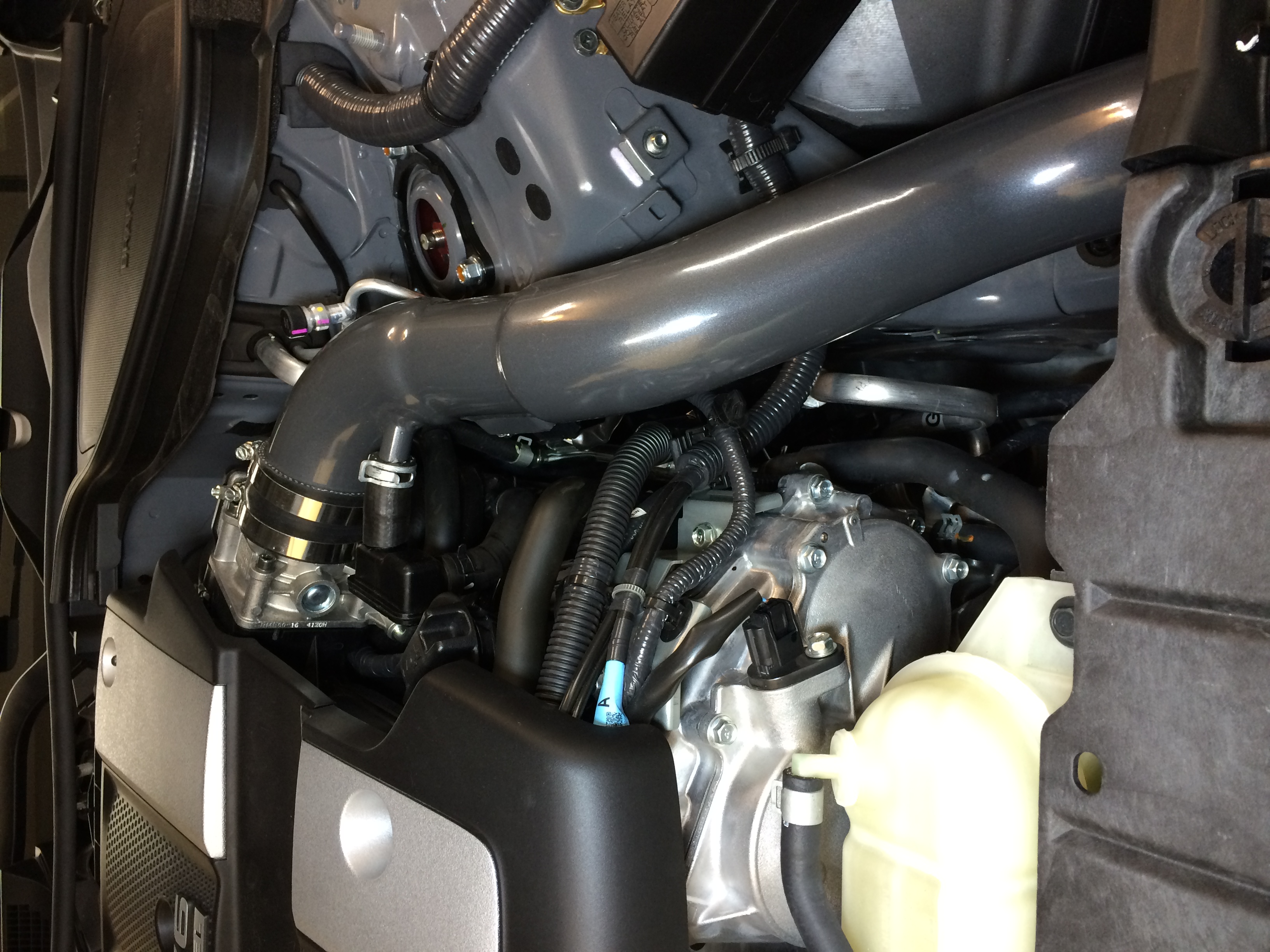
38: Driver’s side you can’t see it all, despite all the suffering!
That was evening 4 which included buttoning up the rest of the things, about 2.5 hours.
Drove it the next day (today, Sunday 5/17) and the steering was clocked about 20 degrees left. A minute into the test drive the car freaked out and applied abs in a wacky way, then threw a light.
Evening 5 (tonight) was spent re-clocking the steering, which mercifully can be done without having to remove anything else.
……….
Test drive was short. My car has the Takeda CAI, garageline midpipe, and stock muffler. Compared to stock manifolds + Berk HFC, it was a fair bit louder on cold start, but maybe only a little louder at normal idle. Louder on the street and it sounds quite a bit different now at high RPM. Dyno’ing tomorrow and seat of the pants it feels like there was a gain in top end – the car always felt a little “choked” up there before (even with HFC) but that seems gone now. However before that I’m having some super-high-flow cats installed just aft of the headers (per SCCA class rules) so the sound may be changing somewhat.
More to come soon, stay tuned!
Bring the Noise
The Bridgestone RE71R tires made it so I could no longer spin the tires everywhere, which means more power is needed.
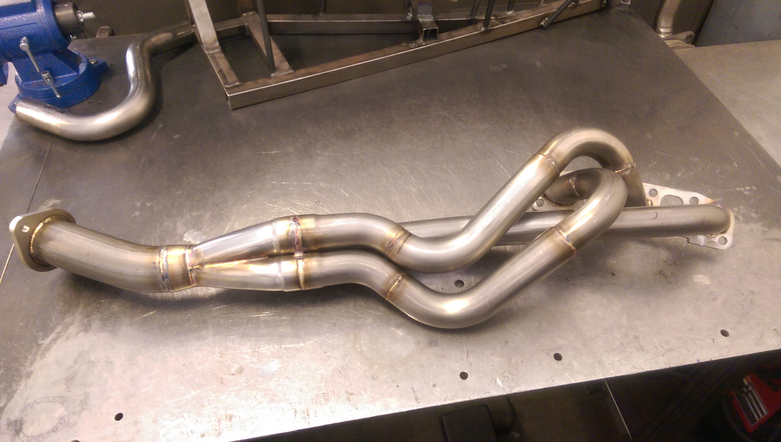
PPE stepped, full stainless, tuned equal-length with 15 degree racing merge collector headers underway – hope to have them on the car next week, with a follow-up tune done before the trip to Spring Nats (Nebraska) over Memorial Day weekend.
Paul @ PPE snapped a pic for me, before they go out for ceramic coating.
Have some other exhaust work that’ll be coinciding, will cover that in a future update.