Why are old Camaros always so slow?
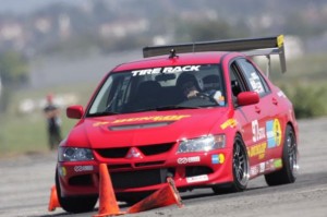
Them be fightin’ words in some circles but since this is my blog, it’s a fair question to ask. The context of the question today, is around why they’re slow in autocross, when seen from the eyes of a typical die-hard SCCA competitor.
One of the more interesting aspects of this project, has been the speculation and conjecture on why the car is going to be slow in STX. As a car builder, one ought to understand their platform, and in leveraging available allowances, do everything possible to minimize the impact of any deficiencies, while accentuating the strengths. We all *know* these Camaros are slow at dodging cones – but what specifically makes them so slow? Some are convinced it’s the axle-tramping rear suspension; others are sure it’s the front suspension, still others think the car won’t really be making good power vs. its competition because of optimistic 60’s SAE Gross vs. today’s Net HP ratings. Or maybe it’s way too big and heavy, maybe the brakes can’t be made to work, maybe the steering is too slow.
Well, I am sure there are many possible reasons, and until I’ve got it running and tuned as well as I think I can, we won’t know which of the above are true. Maybe none of them apply if the car is built right; maybe all of them are true, regardless of all you do (at least within ST rules).
Though I haven’t gotten too far with it yet, there are two Very Big Things I see holding these cars back in the majority of cases, that I’ll address in this post. Hopefully with my advance knowledge of these shortcomings (queue G.I. Joe) and some efforts made in mitigating them, I can overcome. Here they are below, in no particular order-
BIG THING THAT MAKES EVERY AUTOCROSS CAMARO YOU SEE SLOW #1:
The person tuning and driving that Camaro you see, doesn’t know what they’re doing and/or didn’t build their car to “go fast”. Now, I understand that statement comes across as horribly arrogant, but let me explain-
We all (or most guys, at least) tend to think we know what we’re doing the first we get behind the wheel. “Of course I’m an excellent driver”, and we continue to believe it until we see the times of somebody who really is fast.
To use one of my favorite memes in illustration,
| First I was like- |
 |
| so I was like, |
 |
| but then I was like- |
 |
You just don’t tend to see the really fast guys driving old Camaros at SCCA events, and you almost never see the really fast guys at non-SCCA events. They’re often running more modern and closer to stock Miatas or Corvettes, or whatever the hot car is that year. The best drivers tend to flock to the platforms that are believed to be competitive, because they want to win! It’s super rare to see somebody really good (and please, don’t for a second take that to mean I think I am) driving an oddball platform. What this means is the general Good Driver rule still applies to Camaros- a “really good” autocrosser could hop in the driver’s seat of a “beginner/intermediate” Camaro autocrosser, and usually beat them by a few seconds on 50-60 second course. In some ways the non-competitiveness of Camaros, and many other interesting cars, is a self-fulfulling prophecy, as those who own them are likely to get discouraged by their early results and lack of any evidence they’ll ever be competitive, leading them to to not stick with the sport long enough to get any good at it. Who knows, perhaps with some success maybe I can change that – I sure see more Nissan 240sx’s out there today than I saw before 2006.
So there’s the driving element – if the person driving that Camaro wouldn’t be competitive in the Miata or Corvette or whatever, there shouldn’t be any expectation they’ll be fast in the Camaro. Subtract a few seconds for a really great driver, and maybe the car looks a bit less bad?
The other aspect of this relates to tuning and preparing the car to go fast in autocross, and skill in this area almost exactly parallels driving, though most people seem a little more willing to admit their shortcomings in this space.
There is an unbelievable quantity of parts out there for these cars, as they’ve been undergoing speed tweaks for over 44 years now. While as best I can tell the majority of effort into these cars for decades was around drag racing, the idea of making them go fast around corners has become very hot in recent years and the parts variety reflects this. The “handling” renaissance begat a staggering quantity of suspension parts but not a lot of good guidance on what to do with them. Individuality, limitless modification options with no rules boundaries, and differing levels of willingness to sacrifice street manners on the altar of speed, have prevented the crystallization of a “spec” setup for the Camaro. A good example of a spec setup, is that for the super-popular Street-Touring 1989 Civic Si, published by Chris Shenefield about 8 years ago:
http://www.redshiftmotorsports.com/RedShift%20Tech%20Page.htm
With no spec setup to start from and no prior experience assembling a proper-handling autocross car, it’s no mystery so many of these cars end up not working very well, driving aside. The Camaro as a platform is a deep dark hole to climb out of, too difficult to expect anyone to succeed with as their first autocross tuning project. You can put your faith in what your suspension vendors tell you, but their answers are going to be targeted to the middle of their demographic, who may care more (or less) about a comfortable cruising ride, than you do.
There are some people floating around out there in the old-Camaro world who kinda know what they’re doing around the cones, I think, but since there isn’t really any sort of rules in the old-car specific events, it’s impossible to tell who’s doing a lot with a little (bit of modification), or who’s doing less, with a whole lot more. Structure and rules are frowned upon in those circles, which is a shame because it makes results impossible to use in drawing conclusions.
I guess as a message to all my fellow old Camaro owners out there – if you really want to be fast in your Camaro at the autocross (and largely also, the track) – the best thing you could probably do, is park the Camaro for a while. Get a Miata, or an S2000, or a Corvette, and go run a ton of events (SCCA preferably). Figure out who the fast guys are in your region and track your times against theirs. Even better if you get a similar car. By getting a car that’s great out of the box, you can forget about setup and focus on driving. This will teach you the importance of driving, while at the same time familiarizing you with the characteristics of a proper-handling car. When you’re ready, then go back to the Camaro – I suspect the experience gained in a “good” car will better illustrate how far you have to go with your Camaro. It should also help you better understand the importance of different modifications, and get you to spend the next few bucks on tires or shocks, instead of a supercharger.
How am I going to avoid this common problem? By drawing on my experience as a driver and a tuner from many other cars, to dig this thing out of the deep dark hole it starts out in. I don’t have any success stories to look to, but that’s part of the fun/challenge.
BIG THING THAT MAKES EVERY AUTOCROSS CAMARO YOU SEE SLOW #2:
The stock front suspension really is as bad as you’ve heard. There’s a lot of things wrong; below I’ll attempt to explain just one facet of the wrong-ness 🙂
Most of the old Camaros you see at the autocross look awful – they are too soft, and the front suspension looks like it’s doing the opposite of what it should.

Not trying to pick on this car or driver here – this photo pulled from http://www.milesspeed.com/ – a neat site I stumbled across in researching these cars. Car is owned/driven by cool chick Liz Miles, and this was taken very early on in the car’s development. Using it just to illustrate some of what’s wrong with the car’s front end; odds are if you’ve seen an old Camaro on an autocross course, it looked a lot like this.
Here’s another one from a 1967 magazine article on the original Z28:

That thing has no grip on the crap OE tires, but it still manages to showcase how utterly whacked its front suspension is.
Front grip is tremendously important in autocross. At the track if you’ve got way more power than everyone else, you can maybe get away with a pushy (understeering) car, heck, it’s more stable. But not in autocross. You need to generate big yaw/rotation, and you need to be able to change direction quickly. The front tires do all this work and it’s the front suspension’s job to keep the tires as happy as it can.
Pretty much nobody with one of these old cars is giving them enough front tire. I’ve seen cars with $10k+ in aftermarket grafted-on C6 subframes, uber expensive shocks, and mega-$ forged wheels … wrapped in 245 width tires! With 335s out back! That sort of stagger might work on a 911, with over 60% of its weight on the rear axle, but it’s a recipe for terminal understeer (and a frustrating/boring driving experience) in a 55% front-weight Camaro. If you want one of these things to turn, you need to give it all the front wheel/tire you can, and nothing made today with a DOT stamp is “too much”. My Viper had about the same front weight as most of these Camaros, and it had 335s up front! At that size things were just starting to work right. 🙂 Obviously packaging is a problem but with all the effort put into everything else, I don’t see why more of those guys aren’t running at least 285s up front.
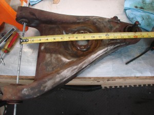
So to the subject of analysis here – the motion ratio – and boy is it TERRIBLE! To many that may not mean anything, so let me attempt to explain. Below is a photo of a stock ’67 Camaro lower control arm. At the far left, the rod illustrates the axis upon which the arm pivots. At a bit past 8.5 inches down the tape measure, are the two bolts that hold the shock. When installed, the spring sits concentrically around the shock. At the far end, just under 16 inches, is the lower ball joint’s pivot point. Though you can’t see it here, there’s a hole for the stock swaybar attachment at about 13.5 inches.
So what’s the motion ratio, and why do I care? Well, the motion ratio, is the ratio between how far the wheel moves, compared to how far the shock absorber (or spring) moves. The further out on the arm the spring/shock attach, the higher (and better) the motion ratio. To calculate the motion ratio, you take the distance from the inner pivot to the spring/shock attachment, and divide it by the distance from inner pivot to lower ball joint pivot. If we round the pictured measurements a bit, we get:
Motion Ratio = 9/16 = .5625
This means, for every inch of wheel movement, we only are going to see .5625″ of spring/shock movement. Okay, so why’s that bad?
It’s bad because we depend on our shocks to damp the motion of both our unsprung (wheel/tire, 1/2 our suspension) and sprung (the rest of the car) weight. The better a job the shock can do, the more consistently loaded our tires will be, the more grip we’ll have, the faster the car will go around the corner, the lower our laptimes. This motion ratio is about 30% lower than the motion ratio of a good modern car.
Below is a pic of a Viper’s front corner – look at how the spring and shock attach waaaaay out on the arm, right next to the lower ball joint: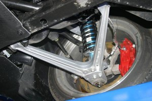
The Viper enjoys a much much better motion ratio than the Camaro.
Shocks depend on velocity to do their job – if they are not moving, they are not displacing fluid, which means they aren’t doing anything. The more shock travel we can get per unit of wheel travel, the better we can control every microscopic bit of that wheel travel. This also allows us to control things with lower shock forces, which makes it easier to find reasonably priced units.
In an autocross car with a good motion ratio, we’re generally looking for what the shock does at about 3 inches/second on a force vs. velocity graph (explained somewhat here: http://farnorthracing.com/autocross_secrets20.html ). Most of the movements the suspension sees on an autocross course are in this speed range, so that’s where we care about what our shocks are doing. Shock velocities above that speed (bumps) are important too but somewhat less so, they’ll be a subject for a later day.
So getting back to the Camaro – with a motion ration of .5625, we’re only getting about 2/3 the shock travel or velocity, of a “good” suspension car. So whereas they get to build their shocks to work at 3 in/sec, ours have to be doing the same quality of control, with 2 in/sec. The problem is, accurate control and large forces at these low shaft speeds, are very hard to come by – any of the common shocks available over-the-counter just aren’t going to get it done, at least not very well. But wait, it gets worse!
Spring rate by itself is a not very good indicator of how stiff a car is – what’s more useful is the “wheel rate”, or maybe the “natural frequency” of a suspension. Here’s an online calculator if you’re interested to find out yours: http://www.racingaspirations.com/?p=292
Those that have ever ridden in an unladen 1-ton pickup truck, and been bounced all around, have experienced a high wheel rate, and a high natural frequency. The high natural frequency is caused by a very high wheel rate, combined with not much weight on the spring (an empty truck bed). If you’ve ever then loaded up that bed with a few thousand pounds and noticed the truck suddenly rode much more comfortably, it’s not because the wheel rate went down (in some leaf systems, it might actually have gone up) – it’s because the natural frequency has gone way way down due to the weight/load in the bed.
We arrive at wheel rate by taking the motion ratio, and multiplying it by itself – “squaring it”, in math terms, then multiplying it by our regular spring rate. In the Camaro’s case, .5625*.5625=.316. That means that for every 1 pound of spring rate, we are going to have .316 pounds of wheel rate.
Wheel rate and natural frequency are concepts you can use to compare the stiffness of any two cars, regardless of suspension type. You’ll often see sliding scales where 1hz is “comfy street car”, 1.5hz, “sporty car”, 2.0hz “race car”, 3.0+hz “race car with aero downforce” – something like that. Those are really just broad generalizations and by no means limits on what you can do with your car.
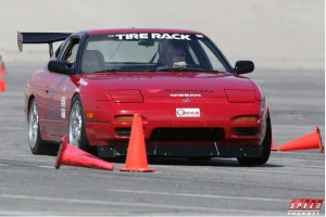 If you’re setting up a car to handle well, 2.0hz isn’t a terrible place to start. If you’ve driven other prepared-suspension cars that you really liked, that were of a similar layout (RWD, FWD, AWD), it might be worthwhile examining that car’s frequencies and consider it as a baseline. For instance, my 240sx used a 550lb. front spring when it was in STS (street tire) trim. It had a bit over 700lbs. of total weight per front corner, about 55lb. unsprung. It used a strut front suspension which granted a motion ratio of about .96. Its 550lb. spring netted a ~500lb wheel rate, and with the car’s weight, its natural frequency was around 2.7hz. While this was way higher than anybody is likely to recommend for a daily driver, it wasn’t terrible on the street, but more importantly, it wasn’t so stiff that the street tire wasn’t working well. The car worked great!
A similar calc on the rear of an STS Civic I built, puts the frequency around 3.5hz! Some guys I know are running springs up in the 4-5hz range on the rear of those cars.
So getting back to the Camaro, now knowing the 240’s numbers (500lb. wheel rate, 2.7hz) as a ballpark. With our Camaro’s motion ratio, to get a 500lb. wheel rate, we’d need (500/.316)=1582lb. springs! Even at that rate, our frequency is only going to be a bit over 2.5hz, in some ways softer than the 240sx. To get to the same frequency I’d need springs up around 1820lb./in!
Ugg, now we’ve got not much shock velocity to control our wheel motion, and on top of it, we’re going to have to run crazy stiff springs to get this thing to the stiffness level we want.
There are a lot of things “less than ideal” about the Camaro’s front end geometry – bump steer, camber curves, etc., that I can’t really fix in ST, and that you can’t really fix with the stock subframe. In an earlier post I mentioned my plan for dealing with these was to set the static numbers good and “not let it move much”. You can see now why people hadn’t really tried that approach before – they couldn’t! No normal shock you could buy off the shelf would damp a 4-digit spring given an equal motion ratio; things that stiff were just outside the bounds of people’s thinking. About the stiffest I’ve seen anyone run is 800lb. springs, for a 250lb. wheel rate, about half what I’ve depicted above. It’s no wonder people were so concerned with bump steer and camber curves – at that low a wheel rate, the suspension would experience large (double to triple) the quantity of travel as the more stiffly sprung version, so the negative effects of bad bumpsteer/camber curves would also be doubled or tripled. It also means they had to run their cars a lot higher, which is a Big Bummer for them, we’ll explore later.
So to bring this home-
Bad motion ratio gives shocks poor control of sprung/unsprung motions, leading to inconsistent tire loading
Bad motion ratio creates a lot of suspension travel at “normal” spring rates, exacerbating the problems with the stock suspension’s camber and bumpsteer curves and necessitating higher front CG
How am I going to avoid letting this screw me up? Simple answer – great shocks! The 28-series Konis I have, were originally designed a few years back for high-downforce Indy cars, where there are very large forces needed at very small suspension displacements. Even though an autocrossing ’67 Camaro is a long ways from a recent Indy car, the characteristics needed end up being quite similar. There are many other high-end brands (Penske, Ohlins, Moton, AST, JRZ, Sachs, and more) than can get this done too, Koni just happens to be the one I’m most familiar with. With a little bit of revalving, they are going to allow me to run these really high spring rates, while maintaining good wheel control, something a lower-end shock wouldn’t.
Lots more wrong with front suspension, more to come on that later…
John Purner and Complete Custom Wheel
Spoke with John Purner of Complete Custom Wheel today. Not quite ready to order anything yet but had a good chat with him about the project and bounced around some ideas. I ran CCW wheels on both my SM 240sx and on the SS Viper. While I haven’t received any sponsorship or special deals from CCW, I always look to them first. Their wheels offer a tremendous value in custom-sized forged wheels, part of why so many racers run them. I also think the “Classic” style they offer would look good on the Camaro-
/Classic/zoomed/1-1024.jpg)
John was having, as he put it, an “average” day. Well, I don’t know if I could have handled him on a good day – he had me laughing so hard I was practically falling out of my chair.
Turns out John and I share a lot of the same viewpoints on things related to these cars. It was refreshing to find someone else who not only thought like I do, but also felt so free to vocalize those thoughts without a Political Correctness filter. Doubly so, as he’s a guy who has a business selling parts to the public, oftentimes people in that position are so reserved in what they say to preserve their “image”.
I don’t know if I’ll be running CCWs on the Camaro. I don’t get anything if you decide to buy some. But you owe it to yourself to at least consider these wheels at the time of your next purchase, the guy is just that cool.
Caswell zinc plating and blue trivalent chromate
One enjoyable aspect of working on cars is taking something funky and making it nice and clean again. With plastic stuff that usually means throwing out the old and buying a new, but with metal, especially decent metal, there’s usually something you can do to “bring it back”, without having to buy a new part. Plus it’s fun to use as much of the original car as possible.
With the 240sx I had a lot of the suspension components powdercoated. Powdercoat is a much more durable finish than paint , available in a variety of colors and textures. Being a thick coating, it adds a little weight, and won’t work anywhere you have tight tolerances, like in a fastener or on two tightly mated surfaces. I plan to have several things on the Camaro powdercoated. RW Little is a place in San Diego I’ve gone to many times that has good prices and reliably quick turnaround.
Since building the 240 I’ve learned about how DIY’ers can apply other sorts of finishes to their metal parts at home. Another very popular coating in automotive applications is cadmium plating. This is often seen in brake boosters but also in some suspension components, on fuel pumps, or carburetors. The cadmium plating offers excellent corrosion resistance, and a neat yellow sheen when new.
Caswell plating has a range of kits to do all sorts of platings and coatings and anodizing at home. Standard cadmium plating involves some very toxic chemicals and is pretty much banned in CA. Caswell has a good alternative, their “Copy Cad” kit. With it, you apply a standard zinc coating, then dip the parts in a trivalent chromate, leaving the parts with a nice sheen. The most popular is the yellow chromate, which ends up leaving the parts looking just like a freshly cad plated part.
The plating kit arrived last Friday so I got to work-
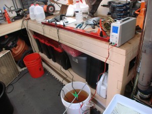
For all of this, you need distilled water. Needed to go to Target anyway, so we loaded up the cart with 15 gallons.
There’s four buckets you need to do this-
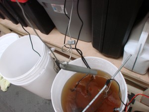
One is a degreaser bucket, orange bucket in the pic below. The degreaser is supplied as a powder to get mixed with distilled water. Parts go in this after they’ve been prepped as a final cleanup stage. This stuff needs to be heated up over 110 to work its best.
Next is a rinse bucket. You use this to rinse the parts after degreasing, and any time you’re moving parts between the other buckets. Mostly you just hold parts over this bucket while spraying them with water to rinse between stages. You can see the edge of the black bucket there, my rinse bin/bucket.
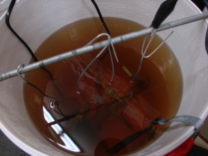
After that they go in to the plating bucket, the white bucket with brown water in it. This bucket gets a bunch of a different powder, and some gnarly brown liquid mixed in. All this stuff is supposed to be pretty safe as far as plating operations go, but note the large box fan to the side. 🙂
The plating bucket gets heated also to about 140. It also gets an agitator pump to keep the fluid circulating within the bucket, which helps the plating process.
The last bucket and step (after another rinse) is the chromating process. Again, this stuff mixes with distilled water. Instead of the old-hat yellow, I opted to go with a blue chromate. It is a little bit less blingy, and a little bit less resistant to corrosion (not that the car is going to see much bad weather ever again), but I like the more understated end result.
To get plating, you suspend the part you wish to plate by a wire. Inside the bucket you place a large-ish sheet of zinc, which you connect to the positive terminal of your power supply. To the negative side, you connect the wire holding the part(s), and away you go. The power supply I’m using goes a bit over 5 amps and is of a constant-current design. Parts stay in the bath for 20-30+ minutes, depending on the size of the part and the desired thickness of the coating.
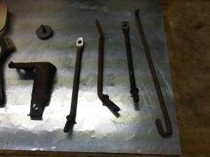
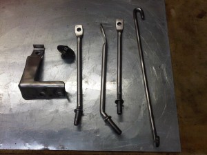
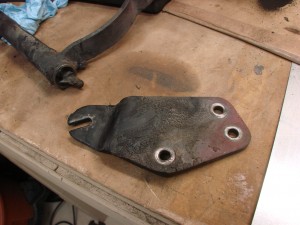
I decided to start off with a few small parts that aren’t really visible, the three “hangers” for the steering column. Mine were filthy and rusty when I pulled them out of the car-
(Sorry for the cell phone pic, left regular camera inside that night)
In with them are a brake bracket, and the underbody emerbency brake assist hanger thing.
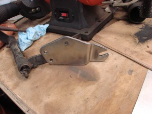
Before the plating process can begin, you need to get the parts down to bare metal. For most of this I used a wire wheel on a bench grinder.
They actually look ok at this point, but left alone, would be back to a rusty funk in very short order.
So into the degreaser, then a rinse, then into the plater. These are some of the clutch mechanism parts I decided to do later, never got a photo of those things in the plating bucket.
Once out of the plating bucket, the parts have a dull gray zinc coating. There is a “brightener” additive available but I didn’t use much of it, didn’t want the parts too shiny.
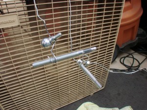
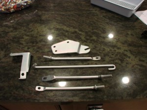
From there a rinse and into the chromate bucket for 30-60 seconds. A final rinse and hung in front of the fan to dry-
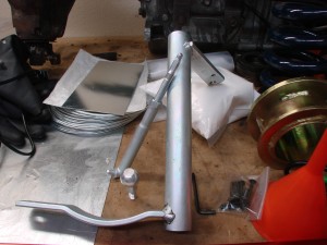
Overall I am pleased with the end results. I don’t quite have the power supply…power to plate the big clutch lever as well as I would have liked. I also didn’t get every last fleck of paint off the original parts, using a bead blaster or sand blaster might have been more effective there than my wire wheel. The pictures don’t capture very well the subtle iridescence of the blue chromate, but it looks quite cool in person.
Here’s some before, during, and after pics of a few parts
This update isn’t totally car related, but other progress is being made, just have to wait for progress updates in other areas. Can see some clues based on doodads visible in some of these pics.
Agricultural 12-bolt and down the rabbit hole
Some of the parts needed for this build are getting harder to find, this is one of them.
The GM 12-bolt is an extremely robust rear-end with an 8.875″ ring gear. It is often compared to the ubiquitous 9″ Ford rearend, the GM piece being a tiny bit less stout, but more efficient (less driveline hp loss).
I’ve been looking for one for a while, and one turned up on Craigslist. The price was good, picked it up Friday.
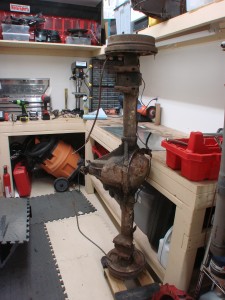
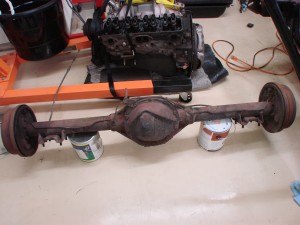
It is a correct ’67-built Camaro piece. According to the owner, it had been sitting in storage for about 20 years, and then in his yard for the past several months. Based on the dirt removed, by several months, he might have meant 120 months!
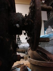
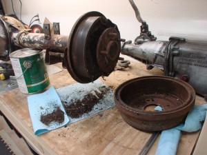
Inside the brake drums, an entire ecosystem was flourishing, all sort of spiders and insect carcasses abounded. In this pic you can see the huge black spider that “owned” the passenger side drum-
I don’t think I should count all that dirt as weight reduction, pretty sure it wasn’t there from the factory 🙂
Getting this thing in shape is going to be a bit of work.
My plan was/is to get the car minimally prepped, so I could take it to a welder and have all the big on-car welding projects done. I have taken a welding class, and have access to a good MIG, but don’t trust myself to weld anything critical, like a live axle lateral suspension locator.
The lateral locating device will be attached to the rear axle, so the axle needs to be clean and ready for welding. I also wish to package the device towards the end(s) of the axle. The limit of how far towards the end the device can be located will be defined by the brakes. Hmmmm…down the rabbit hole we go………..
So it looks like maybe I should get the rear brakes put together to ensure I don’t get welded into a packaging dead-end. Now, STX does have a “big brake kit” allowance. Unfortunately, like many of the ST category’s allowances, it is a rather Fisher-Price allowance (“My First BBK”). I can say that, having spent a few years on the STAC – aka the Street Touring Advisory Committee, the “subject matter expert” rules making/advising group for the ST category. I get what they had in mind – the blingy cross-drilled stuff you see in the tuner magazines that are easy bolt-ons for popular cars. Nothing exotic, no messing with the hydraulic system, nothing requiring any engineering on the part of the ST car builder, just bolt-on kit/kid stuff.
Now, there are plenty of “bolt on” kits for the first-gen Camaro. However, none of them are really designed to work with the factory master cylinder, which is rather large (1.125″ bore). Those kits all come with some kind of late-model Camaro or Corvette master cylinder, often with a proportioning valve.
Can’t change the master cylinder, can’t change the booster, can’t add a proportioning valve – at least, not in the classic fashion. Some first-gen Camaros came with a proportioning valve, but that was only the heavier cars with A/C, not the Z28, and even if it did, I couldn’t change it.
The flexible brake lines I can change, the calipers and bracketry I can change, and I can use any rotor equal to or larger than the diameter of the factory rotor or drum. Even the smallest aftermarket stuff is about 12″ (stock drums are 9.5″) so the diameter won’t be an issue. Since the calipers themselves are free, I was thinking I could use one small proportioning valve right at the inlet to each rear caliper. Then I could say it is part of the caliper and thus legal. I expect to receive emails from people saying “hey, that’s not what they had in mind” shortly 🙂
But I’m not totally sure I even want to have a proportioning valve. The Viper had one when I bought it. I ran it that way for a couple events (nothing National, folks). The car from the factory had shorter front tires than rears, and the previous owner raced it with equal sized tires all around. Taking the car back to Stock, I removed the valve as it wasn’t legal, or needed. When the Viper was on the ideal f/r diameter tires, I thought its brakes were the best of any car I’ve ever driven, and a lot of that was the factory blessing the car with a healthy amount of rear bias. When I ran a slightly (.6″) taller front tire, it would try to kill the driver with too much rear bias. So, suffice it to say, there isn’t a ton of room for error in sizing the brake system, but the proportioning valve does give you a bit more leeway.
I won’t go too far into designing a brake system here, but there are several key variables to consider. In my case, some are fixed, some I know or can estimate, and some are free to change.
Fixed:
Master cylinder bore
Brake pedal ratio
Brake booster ratio
Proportioning
Known/estimated:
Static front weight
Static rear weight
Wheelbase
CG height
Maximum deceleration (use this to calc load on front and rear tires at max decel)
Front and rear tire diameter
Free:
Rotor diameter
Caliper piston area
…from all this there’s a bit of thinking to do. You can design a perfect system on paper, but if the parts don’t exist out there in the world, it doesn’t do much good. Not going to have custom calipers made for this. Have to see what is available from Wilwood, Baer, Brembo, Stoptech, etc., and piece together a working system from their available components. Also have to consider – is the car going to get track time? Autocross puts much less demand on brakes than does the track. Most of my track experience is in the S2000, which had somewhat undersized and undercooled brakes, a constant problem.
If the car isn’t going to see much hot lapping, then 12″ rotors will probably be fine. If it is going to be tracked hard, I’d probably want 14″ rotors, as I plan to run only 18″ wheels, and they’d provide the ultimate in thermal capacity. The bigger rotors are heavier though, a disadvantage at autocross. 13″ rotors might be a good compromise. The larger diameter rotors also provide more brake torque with all else equal.
Speaking of weight, the stock rear drum brakes weighed 43 pounds between the two sides. In my STX Z28 spreadsheet, was anticipating losing 7 pounds in rear brakes, would like to stick to that if possible. Also have to retain some kind of parking brake, which adds weight.
Browsing Wilwood’s brake kit chooser site:
http://www.wilwood.com/BrakeKits/BrakeKitApp.aspx
They ask about the axle offset. Hmm. Didn’t have the axle apart enough last night to get this measurement, and even if I did, am I sure it would be right? I’ll be changing the limited slip, and didn’t know if the axles in there were the stock size and length. So one more trip down the rabbit hole, might as well get my limited slip now, with OEM replacement axles (no donuts here Civic guys! ;)), so I can put all that stuff together and measure my axle offset properly. Will need the measurement to be final and exact regardless of whether or not Wilwood stuff is chosen. They list three sizes, 2.75, 2.81, 2.91. Again, not much room for error here!
Will go into a discussion about the limited slip choice later. One somewhat unfortunate thing, is the GM 12-bolt isn’t the hottest diff out there, so it doesn’t have all the fancy choices some other cars get. I’ve had excellent experiences with ATS/Carbonetic in the IS300 and 240SX, and the OS Giken has gained huge popularity in autocross circles as of late. Still, there are some tried-and-true options for this car I think I can make work fine.
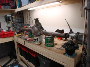
So I got things a bit further along today. Didn’t try measuring the axle offset, figured the bug guts might throw it off by .06″ anyway.. 🙂
Whole thing covered in funk and some kind of white paint, got most of it off. As bad as it looked on the outside, the insides look great. Everything very straight and true, turning very smoothly. It had a 3.07 open diff in it, so it’s not likely to have seen much heavy use. The gears all looked better than any of the Viper diffs I’d worked on!
Oh, and speaking of gears, one cool thing about old cars, is you had LOTS of choices-
http://camaros.org/drivetrain.shtml#AxleCodes
…and the Z28 could be ordered from the factory (unlike the dealer-installed cowl-induction or header options) with just about any of them. 3.73 standard. These days, you have to order a whole big option package or something to get a different rear ratio, you never get to choose it individually.
Spoiled no more
As mentioned earlier, the rules are constantly changing within the SCCA, and the ST category (which includes my STX class) is no exception.
Today the November 2010 “Fastrack” was released:
http://www.scca.com/documents/Fastrack/10/10-fastrack-solo-solo.pdf
In it was the announcement that the suggestion to remove 14.2.F was made to the SCCA’s BOD (Board of Directors). The BOD oversee all of SCCA and for the most part, aren’t interested in Solo (autocross). With Club Racing and Pro Racing, we’re sort of the redheaded stepchildren amonst SCCA members, not receiving much attention from the top. In a lot of ways this is for the best, as the recommendations made by the SEB (Solo Events Board) are generally “rubber stamped” by the BOD and we go on our merry way.
As mentioned in the post about my racing background, I have been lobbying for the removal of the aero/body-kit allowance from Street Touring since late 2003. As you can see from my exploits, this stance is clearly not because I don’t enjoy, or find interesting, or find worthwhile from a performance perspective, aero components on autocross cars. I absolutely do. The thing is, I don’t think they belong on Street Touring cars. ST is a great category because it allows you to do enough to make your car work really really well, without making you do stuff that you don’t want to do. Aero is one of those things that can help, especially the lighter cars, but it’s not going to “fix” anything about the car from its Stock form. Not when our average speed is 40mph. There’s been room to do some really wacky stuff for years, and thanks in a large part to the efforts of Team Undercoat Racing at the 2009 Nationals, it looks like ST’s aero allowances are FINALLY going away! A big thanks to them, and to our STAC members (especially Andy Hollis who has been the movement’s most prominent evangelist), and to everyone who wrote in asking for the change.
Of course, whenever there is a change like this, not everyone wins, or is pleased. Among those against those change were buddy Rick Jung, who has built one of the fastest STU Evos in the country, and who put a lot of work into designing a really nice 2-element wing legal for ST, that’s found its way onto a lot of the top STX, STR, and STU cars-
So here’s a shout-out to Rick. I think he’s still making and selling the wings, which I’ve seen successfully used on some Street Modified and Modified-level autocross cars. If you’re in one of those classes and need a great wing give him a ring! http://cirodesign.com/
So….as to how this change impacts the Camaro…
I’d originally envisioned running the car with the original style rear spoiler, because I like those sorts of things, and I think the car looks much better with it. I don’t think it would have made any measurable difference at autocross speeds. Heck, even the huge wing I ran on the 240sx, I couldn’t tell a difference at our average autocross speed (40-43mph on most courses). And no, I wasn’t planning on any enormous wing or spoiler for this thing – I think Penske got the look right and other than larger-diameter wheels and maybe a lower ride height, I plan to deviate from that look as little as possible.
But, believe it or not, the rear spoiler you almost always see on first-gen Camaros was never offered as a factory-installed option in ’67; you could only get them dealer installed. That means I can’t run it in STX in 2011 on the car, unless somehow the rule change either doesn’t go through.
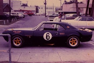
Had planned on running the car in a couple different “trims” depending on the event. I think the car looks a little better without its bumpers too, but of course one must run them in STX. So for SCCA, the trim will be no spoilers and both bumpers. If I take the car to a non-SCCA event, then I’ll probably run both a front and rear spoiler, but no bumpers. Will have to come up with a way of making the rear spoiler removable, without leaving ugly holes in the trunklid. Maybe incorporate some trunk latch pins to the spoiler mounting scheme, making it look even more like a Penske car. 🙂 Even the earliest pictures I’ve been able to find of their Z28s, all have the rear spoiler. Here’s one of the car prepped for Sebring, the second race of ’67-
Car came with a spoiler so I weighed it tonight,
about 6.5 pounds. Doesn’t sound like a lot of weight right now, but I know how hard it is to get chunks of weight that big out of a car after you’ve done the “big ticket” items (spare/tools/jack, seats, battery, and exhaust). At some point I’ll be scrounging for a quarter pound or less, making this seem huge.
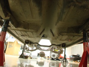
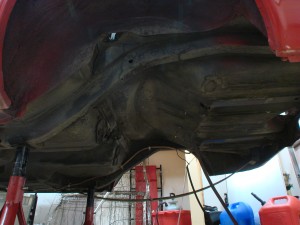
Underside of the car is all cleared up, ready for the work to begin. Interior is *almost* done, just need to remove a few more pieces of door and window guts.
Getting there!
Sound deadener no more
It seems popular to add extra sound deadening in these old cars. This was no exception, it had a whole bunch of randomly applied sticky asphalt-based stuff all over the place, underneath the original factory sound deadener. Car might have had a big stereo in it at one point, who knows.
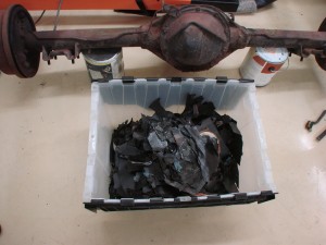
Finished scraping the last bit of it out tonight. Managed to collect most of it in a bin-
Over 24 pounds! So no net savings over the car’s factory weight, but nice to remove some of the chubbiness it’s put on in reaching middle age… 🙂
Almost done taking things apart
The rear end from this car is GM’s lighter-duty “10-bolt” axle. While it’d probably be able to hold up to the power I’ll be making with the tires I’ll be using, the Z28 came with a 12-bolt so that’s what I need to get. The 10-bolt came out today-
Sucker is heavy, I didn’t weight it, but 120-130 pounds is probably about right. I peeked under the drums, the rear shoes were worn down to their rivets. Wonder if they’re the originals?? Haha. I tried not to get too close, there’s probably asbestos in them, not to mention all sorts of other places.
With the axle out of the way I also pulled the fuel tank. Figured with all the welding about to happen back there, didn’t think it’d be a good idea to have 10 gallons of it in there. Instead of siphoning I pulled the tank out with the gas in it, and poured into spare cans. Lots of room back under there with all that stuff out of the way.
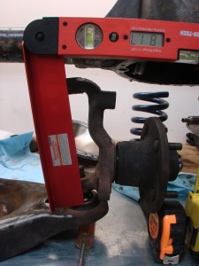
Played around a bit with the front suspension, see what sort of bump travel I’ll have available. It looks like it actually starts to curve the right way at the extreme of bump travel, will have to see if I can actually operate there. Was thinking I’d need to find a donor 265/35-18 tire for test fitment, but checked and found the 245/60-14 tires I got with the car, are actually the same diameter! Obviously the “real” tires will be an inch or so wider, but this should help get the suspension travel range in the ballpark.
Found a smokin’ good deal on the driver seat I’ve always wanted. It showed up a few days early, so that was a nice bonus. Won’t be showing it off ’til it’s all mounted in the car.
Not a whole lot left to do in teardown. Going to leave the steering intact for now to make it easier to get the car on the trailer. Need to finish pulling the brake hardlines and stripping the interior. Need to acquire a 12-bolt, then get it going on the road to re-assembly!
Non-terminal steelitis
Some cars are really good from the factory and need little help to be made made super good. Other cars are not so blessed, and need lots of help.
Something I’ve seen a lot of in modern performance cars, particularly turbocharged ones, is a proliferation of “magic little boxes”. One of them is a manual boost controller. Another is a turbo timer. Then there’s the other one to play with the A/F tuning and cam timing. Before you know it, there’s half a dozen little black-box warts all over the interior with their knobs and wires everywhere. Yuck! I hate that sort of clutter, magicboxitis you might call it.
“-itis” is often used as a suffix to describe an inflammation of the -whatever, maybe it’s the tonsils or the colon.
The thing I’ve seen happen with these old muscle cars is a sort of steelitis. The answer to almost every problem is to bolt or weld in some beefy looking steel braces. Subframe connectors, watts links mounts, additional crossmembers for conversion to 3 or 4-link, roll cages, and extra tubes and braces in the engine compartment. Certainly, when done right using good straight paths, these things can be helpful and effective, but so often the cars end up like tanks – strong but heavy. Leaving one to wonder if the car is really any faster than it would have been with a flexible chassis, minus the 200lbs. of steelitis.
A big goal for this car is to keep the weight as low as possible – both in quantity and location :). I’m going to be competing with better-balanced cars on the same size wheel/tire (well, many of the BMWs run 255s, but it’s close), so I have to do everything possible to keep my weight in the same range as them. The RX8s are 26xx with about 50/50 weight distribution, the BMWs in the mid to low 2800’s also around 50/50 and the Subaru WRX in the mid 2800’s, with AWD, but nose-heavy and on 245’s.
I had a huge 33% (650lb.) weight disadvantage to the Civics when I ran the 240sx in STS, but I had some big advantages there too in bigger/better tires and RWD. I think I can get the Camaro’s race weight a lot closer to the BMW and WRX weight than people would expect. Doing so will be critical as I won’t have any sort of tire or drive type advantage.
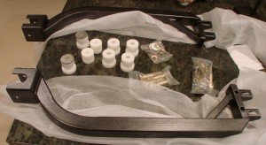
To make it light, I will have to aggressively treat any steelitis flareups that occur, which is difficult because there are lots of pretty steel parts out there begging to be put on the car. One slipped past my steelitis immune system today, the subframe connectors-
Actually I had made up my mind weeks ago to use these parts, and having them in hand was a prerequisite to the first big set of work I’m having done by someone else, which should be starting in a couple more weeks.
ST allows for bolt-in subframe connectors, which these are. From a design perspective, I like them for a few reasons – one is they tuck up nicely next to the rockers, which should make it easier to get a good middle point of attachment between the SFC and rocker panel. It also reduces the ground clearance hit from the parts; the car is going to be very low, and with the limo like 108″+ wheelbase, the car is going to want to high-center getting on trailers and stuff. They’ll also make it a piece of cake to jack up the car from the side.
But man, the pair weigh 24 pounds!! See, that undoes my 11lbs. of weight savings in rear springs, and another 13 pounds of savings from the HVAC system. On the steelitis mitigating side, they are sprung weight, very very low in the car, fully between the axles so the “cost” of that weight is about as low as it gets, but still, ouch.
A quick aside about chassis stiffness. People tend to go overly gaga about chassis stiffness and torsional rigidity. The new Ferrari has 1x,xxx ft-lbs/degree of stiffness, the McLaren has this, that, whatever. While important, I think it tends to be mostly overrated as a goal for people working with autocross cars, particularly those that won’t be running on big wide slicks. The reason we need chassis stiffness is so that our suspension tuning actually does something. If we want one end of the car to offer relatively more roll resistance than the other, our tuning efforts will be stymied if our stiffening of that end gets absorbed by additional twist in the chassis. If the car is responsive, has the balance you want, and is generally predictable to drive, then you aren’t going to find a ton of time in additional chassis stiffness. In most cases, you will probably make the car slower, as the additional stiffness comes at a huge weight penalty when the car builder succumbs to terminal steelitis in the form of multiple strut tower bars, fender braces, 24-point roll cages, etc.
One other thing to note in the picture above, the little white cylinders. Those are delrin bushings for the front subframe. Delrin is a hard and durable plastic that doesn’t really compress, unlike the rubber bushings used in those spots by the factory. In conjunction with the subframe connectors, those little guys will do a lot to “lock” the front subframe to the body of the car, and add some stiffness to the overall structure. If our rules were more open I’d probably use aluminum in those spots because it’s a bit tougher, but we aren’t allowed to use metal bushings. The Delrin should be fine really. These bushings aren’t the whole subframe/body interlock story, there’ll be more coming later, stuff I’m still working on.
Already have an engine builder involved? That was quick. How hard was it to find an original block? Isn’t the ’67 a small journal? Or had they moved to large journal by then?
The ’67 block was small journal with 2-bolt mains, they moved to large journal in ’68. Small journal maybe not as reliable or as long-lived in a roadracing environment, but should last plenty long in autocross and actually make a couple more hp in the process.
It’s not hard to find an original block. In ’67 the 3892657 block was used by many motors, there was nothing special about its implementation in a 302.
http://camaros.org/drivetrain.shtml#BlockCast
The engine build has been in progress since before the car was acquired, as I figured it would be one of the more tricky and time-consuming aspects of the build. I’m hoping for it to be done by Thanksgiving but Christmas is more likely. Not really a problem as the rest of the car will need a bunch more time than that.
The engine builder was chosen for their long history building successful engines under the SCCA’s strict rulesets, and also for many of those engines being small block Chevys. The latter aspect affords them a great inventory of parts and connections to others who have parts.
Jerry MacNeish
This Jerry guy knows a lot about these cars. He’s been playing with them since before I was born and in doing so has amassed a pretty crazy knowledge base. Jerry is to Camaros as famed autocrosser Andy Hollis is to the Honda Civic/CRX.
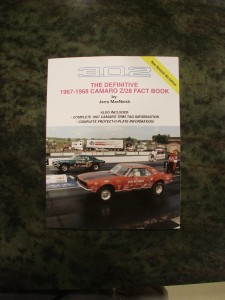
A couple things from Jerry showed up today. First was his book,
“THE DEFINITIVE 1967-1968 CAMARO Z/28 FACT BOOK”
Lots of good details, all Z28 specific, will help ensure I get all the little brackets and details correct. Also confirmed (positively, yay!) a lingering gearing availability question I had.
Link to his books – http://www.z28camaro.com/publications.html
While you’re there, check out this car:
http://www.z28camaro.com/unrest68.html
There’s no shortage of myth and legend of what these cars could do from the factory down the quarter mile. Some say they dogged off the line and couldn’t break 15 seconds in the quarter. Others brag of running 10’s with slicks and headers. Any time you hear stories like this, reality probably lies somewhere between. Jerry’s numbers on that page are pretty good on a car with only a couple little ST-ish things done from the factory. This STX car when done should make a little more power and weigh a good 200 pounds less. 🙂
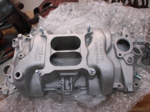
The other thing in the box was an original mint-condition intake manifold for the car. It was supposed to go straight to the engine builder but what the heck, this gives me a chance to photograph it before the motor is all put together.
Can’t wait to be done with all the dirty scummy parts, and start putting together the nice clean new stuff.
